Jurek and the Amazing Techno, Colored DreamWall

Jurek and the Amazing Techno, Colored DreamWall

The title is mostly a placeholder, as I haven't really figured out a name for it yet. This project is a wall hanging that consists of semi-large triangular pixels using discrete RGB LED's and PWM to control intensity levels of each LED, resulting in a 4096-color display.

Tuesday, September 11, 2007

Miniwall Progress

Pictures
As promised, I come with pictures!


Altered Esthetics progress
I got a bit more done tonight--mainly alignment & fine-tuning of the locations of the dividers. None of them are placed on any sort of grid or in a regular fashion, so I've got to go just on my small scale drawing. I got 5 pieces cut and placed, out of a total of about 12-14. None of them are permanently placed yet; I'm still fiddling around with different aspects of the entire construction. I've got 3 other pieces cut and sorta placed, too, but they intersect the 5 pieces I've already got placed, so I'm holding off on those until I know better exactly where they're going (by placing all the other non-intersecting ones).

You can see lots of tape and glue seams in the floor of the base; they're there because the foamcore boards I have are only 20"x30" and the sign is 36"x36". Also, I had to sort-of conserve boards, because I was about 1 short from what I could have used ideally. That's why there are all those weirdly-shaped pieces (look at the tape and glue lines).

The entire thing is 2" high & the dividers are 1" high. The foamcore is 3/16" thick, leaving me just under 3/4" underneath the floor for the circuitry and wiring.

Overall, it's still very, very light and a bit flimsy. Once I attach these dividers, it should stiffen up a lot. If not, and I need to stabilize it more, I can always lay down & glue strips of more foamcore or thin plywood to the underside of it.

Labels: ,

Thursday, August 30, 2007

Summer Slumps

Lack of Updates
Well, seeing as how I completely missed July for postings, I feel it necessary to post now before I completely miss August as well, if even just to make a post about nothing.

Not much has happened with progress since June, because of several reasons. There was about 2 weeks of vacation and work travel in the middle, I changed jobs, and just have been generally not feeling anxious to work on things during the summer in a studio without air conditioning. It's in a basement, which helps the heat a bit, but it's still quite humid there. Perhaps I'll have to pick up a cheap dehumidifier.

However, there has been a little progress. I've been making some headway into the lighted sign construction for Altered Esthetics. Right now, I've got a simple exterior box, and I'm currently working on attaching the floor to it. That doesn't sound like much, but the box is 36" square, and the foam core I'm working with is only 30"x20". This leaves quite a few seams to join everything together. For the exterior walls, I used hot glue to attach the pieces to each other. For the joints on the corners, as well as seaming together the interior floor, I've just been using painter's tape. I'll see if something more permanent (or less blue) is going to be required. I hope not, because the tape is really handy.

I will get some pictures the next time I work on it, I swear!

Until next time...

Labels: ,

Tuesday, May 29, 2007

Testing Update

Workspace
This is a fairly small update -- not much has been happening lately, mainly because the 'wall is still at the Center Earth studio.

I bought some rope, pullies, tie-downs, and clips to mount in the workspace so I can hoist up the wall and work on it while it is vertical, but also still have good access to the back of it. When I was building it before, it was always troublesome to shift it around and get at the cabling in the back while also requiring to look at the top of it (for the pixels).

I usually ended up either blocking it up on some pieces of wood or large batteries, which generally left it just balancing there, or horizontal on sawhorses and counter-weighted on one end. I had to counter-weight it because I needed access to the back, which was hinged in the exact middle of the pixels. The power supply shadow box extended beyond that and added a bit more weight, making it more bottom heavy. The counterweights also obscured several of the pixels, making it slightly harder to debug wiring, soldering, and coding problems.

The setup that I'm working on now will get rid of all of these issues. The only problem I think I may have will be with being able to muscle the wall into position. If it becomes a bigger issue, I will have to rig up a block-and-tackle assembly to make it easier.

Pictures when I get it done...


Construction
The gluing has finally finished on the small 20-pixel test box, so I can finally start playing around with different combinations of things (e.g. 3-color LED's, different reflectors, different positioning of the LEDs). More will come with time.


Soldering
There were 2 driver boards that each had a single LED not working, so I spent a little time resoldering the pin on each of them, so they will both hopefully work now.

Labels: , ,

Wednesday, March 14, 2007

Small Update

Soldering

So, I actually got a small amount of soldering done last night and tonight. I got 2 more driver boards soldered up, one of which I tested a small amount. The one I tested seems to be working, for the most part so far. I verified that the chips are all able to communicate with the microcontroller, and that at least one of the LED output channels works for each chip.
Things went pretty smoothly overall with the soldering, mainly because I ordered and was using brand new 0.01" soldering tips. Two down and 4 more to go!

Construction

Very little progress has been made on the for-test 20-pixel box. I have 2 of the10 sides glued on. Things are gong fine with it, just very slowly. I hope to get it to the point where I can test the 3-color LED's relatively soon. I can pull the microcontroller out of the big LED wall to test with until I get another board soldered up.


TTFN

Labels: ,

Saturday, February 24, 2007

Miscellaneous Progress

Test Module
Progress continues on the smaller test module that I mentioned in my previous post.
I've got the pixel divider walls and the backing glued together, and I tested using aluminum tape on the floor of the pixels. As it turns out, Home Depot stopped carrying the 2'x4' 1/8" white marker board, and now only carry a brown version of it. It's not nearly as glossy (plus, it's brown), so I'm attempting to use the aluminum tape as a reflective agent on the floor as well.

The small number of pixels, combined with the assembly method I have, actually makes this small one not very easy to keep "true", as far as the pixel shapes are concerned. There are only 2 triangles that end up being "perfect", and they're not adjacent to each other (only kissing), so everything kinda wobbled around a little, until I got the floor glued to it.

Soldering
I started into soldering up another driver board, mainly to get myself back into things. The only components I got soldered onto the board were 2 resistors and 2 capacitors. The tip I had used for the first time around is basically useless for the very small-pitch components. It's gotten so built up with debris, and has probably had the tip melted or broken off, so it's not nearly as fine as I need it to be. I'll need to order about 5 of those bad-boys to keep me in stock.

Design
I just got a new tablet PC on Thursday and finally got that up and running. I got all of my development tools installed, brought the tablet over to the work space, and hooked it up to the processor to make sure everything works. It still does, thankfully, and having a small portable communication medium for programming it will be a great help. I also put the visualization Python code on it and tested it out for performance. It runs at about 1/2-1/3 the speed as my desktop, peaking at about 25ms per frame at the highest resolution, so I think it should be fine for "production" use.

I need to start writing more with that code, so other people can start playing around with it. It's pretty rudimentary right now, but I hope to get it to the point where patterns, shapes, text, etc. can be made as individual files and then loaded on the fly.

Media
OK, so you gotta start out small, I guess. I was contacted by one of the writer/director/producers of an up-coming short show called Center Earth about using the technowall as part of background for various scenes. Shooting is slated to start in mid April, and the wall will probably be needed some time in May-ish. There's not much more to say about it yet, but I'll keep everyone posted about progress with it.

Labels: , , ,

Tuesday, September 19, 2006

Shiney!

Construction


All together now... "OOooooo... shiney!"

As an added bonus...

LEDs relaxing in their natural habitat:

Little do they know of the terror that awaits them...

I've spent about 18 hours in the last week working on this and have used about 70 yards of aluminum tape to do this module. My fingers are a bit sore and dry, but at least it's done!

I've also briefly been playing around with a new method of attaching the acrylic to the wall. My latest idea is to use velcro along the pixel borders with the opposite velcro side on the contact paper/acrylic. The narrowest/longest velcro combination I could find was 5/8" wide, which is pretty wide compared to the 1/4" wide pixel divisions I have. I can cut 3 strips out of it and they work just about right.
At first, I just tried gluing the velcro to the wood, but that didn't work worth a damn. The glue soaked right through the wood and seeped through the velcro. Then I got the idea to put the aluminum tape on the top of the wood. (This testing was before I set out to cover the entire wall with tape) Gluing this way worked decently, but still not as good as I hoped. My most-recent incarnation involves glue for the most part, plus several staples along the length of the piece to really hold it in place.
To offset the gap created by the velcro (I don't really need velcro across every single division, and the edges are 1/8", which is far too narrow for the velcro), I also bought a bunch of black felt to glue on both the pixel divisions and the contact paper/acrylic. Hopefully, the combination of the velcro and the felt will create a light-blocking barrier on the top of the wall.

You can see the velcro (and felt) in the pictures. It's the black strips along the different parts, on the top.

I have also left 7 (should be 8, but I got a little ahead of myself) pixels untaped, as these are the potential locations of the distance sensors. I've still not tested them at all, so they may not happen, but I would really like to use them.

Labels:

Sunday, September 10, 2006

Acrylic Progress

Construction
I spent a few hours today cleaning up the piece of acrylic I had cut before I moved. It was a little (1/8") too large on one side, so I went to town sanding it down to be flush. Even 0.1" acrylic is dense stuff, and it took quite a bit of elbow grease to get it sanded down properly.

After that, I decided it was time to apply contact paper to the acrylic. Now's as good a time as any and I'm not getting any younger. Each of the two pieces of acrylic needs two pieces of contact paper. The contact paper is only 12" wide and the acrylic is 19" wide. That's just fine, because I can use the middle of the acrylic for the seam, as that runs along a pixel division anyway.
The first piece I tried to apply was a complete failure. I tried to align the long edge all at once and kept having to peel it back up and re-stick it down. After a couple tries like this, I noticed that the paper was stretching from the forces (the adhesive is pretty strong, plus the acrylic and contact paper were creating a static attraction as well).
For my second attempt, I aligned one end, the short direction, and squeegeed a small (4"?) of it to the acrylic. Then I slowly peeled the backing off while keeping the paper taut and using the squeegee as I gradually stuck the paper to the acrylic. This worked "OK" and left managable air bubbles that I could deal with.
The second half of the acrylic went on so much easier. I had very few air bubbles and no stretching or ripping.

I also cut the second piece of acrylic and affixed more contact paper to it, with similar results to the first one. Now I have a wonderful white box. It's a little odd how completely white it is (only the bottom edge, 1/4" thick from the peg board, is not white). Reminds me a little of an Apple product.


Wall with acrylicAcrylic pieces with contact paperClose-up of pixel with aluminum tape

Labels:

Wednesday, August 02, 2006

Progress Update & Pictures

Good evening everyone!
I've made some good progress since the last post *ahem* a week and a half ago. I've not gotten a lot of soldering done, as temperatures have been well into the 90's for quite a while and I do not have an air conditioner installed in my current abode.

However, that has not stopped progress in other areas, namely

Construction
Here's a frontal and side view of the current progress (with ruler for scale):
Front


Side


I cut and attached the second piece of pegboard to the spare 1x3, again with 2 hinges. This leaves the horizontal split, as seen here:


I have taken the undoable step of gluing the 1x3 to the floor of the back cavity, using Liquid Nailz (but of course!).
The following three pictures show the top and bottom cavity, as well as the 1x3 and the wiring channels I've dug into the wood:

Top Cavity

Bottom Cavity

Close-up


In the bottom cavity picture, you can also see the shadow box, which will house the power supply and any other necessary power parts.


The last thing I've done is cut a hole for the power plug-and-switch plate. In the end, the hole is slightly too large in one direction; I may have to plug it up with some glue or something when I finally secure the plate to the wall.

Shadow Box


Power Plate and Power Supply


I finally decided it was time to get an actual weight estimate for this puppy.
Weighing


Much to my surprise, it is currently tipping the scales at about 35 pounds! And this is without the acrylic on it! I did a quick weighing with an uncut piece of acrylic (1 of 2 needed for each module), it was almost 50 pounds. I may have to drop the acrylic thickness from 1/4" to 1/8" or 1/16". I don't really need the thickness for anything anyway.

Oh well, now I have a few square feet of 1/4" acrylic for any random projects that pop up.
Anyone want to buy it, cheap?

Labels:

Saturday, July 22, 2006

Progress Update

Wow, 3 whole weeks since the last post! Man, people might start thinking the 'blog (and project) is dead.

LED soldering
12 more done, making 112 of 240 (47.6%). I've made some small progress on making more "supplies", like twisted pair sections, heatshrink lengths, and LED & resistor lead trimming, but haven't started soldering any new ones yet.

Construction
I've made a bit more progress in this department (probably more so than the soldering).

I finished cutting one of the two back pieces of pegboard and attached it, via hinges, to a spare piece of wood from the previous construction attempts. This marks the very first metal used in this new design! The hinges split the module horizontally, so the two pieces of pegboard will pivot the same way as well. The hinged back provides me access to all of the electronics once it's done.
I still haven't entirely figured out how to secure the other end of the pegboard yet. The piece that's cut is on the top, and this piece needs to be load bearing. This means that I need to make it secure to the other floor and not just the sides (as they're just glued to the internal floor and provide no structural stability).
My current thinking is to attach several L-brackets to the pegboard and a few to the internal floor as well. Then a metal dowel could be fed through a hole in one side of the sidewall to latch everything together. The only problem is that the L-brackets have to be very small, as the gap is < 1".

Also today, I got 3 scrap pieces of wood (same scrap wood that I used to attach the hinges and pegboard to) glued to the bottom side wall, to make a region for the shadow box. This shadow box, if you may remember, is going to hold the power supply.

That is all for now. The glue is drying as I type, so I'm about done for today. It needs a good 24 hours to properly cure.

Labels: ,

Saturday, July 01, 2006

Progress Update

Construction
I cut and attached another 7 pieces of marker board today; 6 side pieces and the smaller bottom piece. This smaller piece will separate the pixels from where the power supply will reside. I still haven't quite figured out how to construct the bottom box, as it needs to attach to the existing wall (and, indeed, be part of it). I thought I had it all figured out, but after attaching the bottom piece today, I realized that there is no support for anything.

Pictures
As (sorta) promised, here are a bunch of pictures with the latest progress (the last ones were back in April!):

100 soldered LED wire segments:

The differently-patterned bands near the header indicate how long each wire segment is.
  • Black is 2" (12 done)
  • Tan is 6" (41 done)
  • Tan-Black-Tan is 8" (17 done)
  • Blue-Tan-Black-Tan-Blue is 12" (30 done)
Not pictured (because I haven't made any yet) are:
  • Blue is 5"
  • Blue-Black-Blue is 4"

Current construction status:
Front view, showing wire holes and side pieces (4 still need to be attached at the bottom)


View showing the back side (the floor you see is the back side of the white marker board). The height of the outside walls, visible on the top and right of the picture, is a little under 1 inch. Also visible is my wonderful joint-gluing work, using Liquid Nailz.


Side view, near the bottom of the wall, where there still needs to be two pieces attached. This shows the entire height (depth, really) of everything. The marker board visible on the extreme left is 3" tall. The plywood pixel dividers at the middle/bottom are 2" tall. The shorter bottom marker board piece that's barely visible along the back edge is 2.5" tall.

Labels:

Sunday, June 11, 2006

More soldering and gluing

Soldering
12 more (2") LED triplets soldered. 88 done, 152 to go. The 2" sections were kinda tricky, because the wire length was so small and the heatshrink tubing needed to be a certian length just to go over everthing properly. I ended up having to rearrange a few steps in the process to get everything assembled correctly.


Gluing (a.k.a. Construction)
I cut and glued 4 more pieces to the outside of the 1st module. They were all 3"x5.5" pieces. That leaves another 10 pieces on the outside zig-zag part left to cut and apply. For this module, I also need to make room for the battery pack, so I have to extend the bottom side pieces an extra bit, plus have a second long piece on the bottom. The exact dimensions are yet to be determined (I haven't been ambitious enough to sit down and do the measurements). It involves angles and what-not so it's not entirely nontrivial (yay double negatives! Me fail english? That's unpossible!).

Parts
I also ordered 170 2x2 connector housings (sockets) and 500 crimp connectors. The connectors weighed in at a whopping $1.28 each, so the total order ended up being over $250 for just those items (the crimp connectors are very cheap).

This last Digikey order put me near $5k ($4.8k). Lots more to come in that department though. Yet another milestone, I guess. Or something.
*watches as his wallet bleeds more*

Labels: , ,

Thursday, June 01, 2006

Construction and Parts

Construction
Over Memorial Day weekend, I got some decent progress made on the construction. I got one of the long 3" external pieces cut and managed to attach it and two of the shorter pieces to the wall. These pieces are 1/8" marker board, so when two modules are abutted, the common pixel separation will be 1/4", which is what the inter-pixel divisions are in a single module.
I used Liquid Nailz to attach them to the wall, as 1/4" is far too thin to attach anything using nails or screws and I'm not sure how the marker board would hold up to a lot of drilling and pounding. It's holding up well so far, as I've used the Liquid Nailz as basically cement, and I went back in and filled in all the joints with even more.

I also drilled and slotted the remaining 60 holes needed for the LED cables. This went really quick, because I could use the previous 60 holes as a guide.

Parts
With all this progress comes even more parts ordering. I ran out of 1/8" heatshrink tubing, so I bought another 60' of that, as well as some caulk, more Liquid Nailz (used above), and some clear Liquid Nailz, in case the clear caulk doesn't work too well in attaching the LEDs to the wall. I also ordered and, today, received 525 more LEDs from SuperBrightLEDs. I ordered 175 of each color, along with the 90 I already have (about 10 were used as "engineering samples"), should leave me with enough to complete the project and a few left over in case I screw something up.

I will need to order some more 2x2 socket headers and some more 4-conductor wire soon as well, as I am quite short on what I need.

Labels: ,

Saturday, April 22, 2006

Progress Update

LED Triplets
17 more done, leaving 193 left to go. I probably won't need many more triplets with 12" 4-conductor sections. They're quite long and way more than I need for most of the pixels.

Construction
I've made 60 holes (half of what I need) in the section I have (mostly) constructed. One per pixel, each slightly larger than 1/4". The largest drill bit I have is 1/4" and one LED head fits through just fine, but I need to feed the other two LED heads through as well, the last of which also has 4 wires to contend with as well. A few swipes with a circular file slots the hole well enough to fit everything fine.

That is all. Nothing major, just more busywork.

Labels: ,

Sunday, April 02, 2006

More updates

LEDs
16 of 240 done... decent progress on the next 14


Construction
I've got both the backing pieces cut, along with the zig-zag edging on one side of each of them. I also attached them to the lattice with liquid nailz. Perhaps it was a little overkill to use that over wood glue, but I wasn't entirely sure how well the wood glue would adhere to the marker board; it's pretty smooth and wouldn't take the glue like normal wood would (hah!).

I ended up buying another dozen (!!!) clamps to make sure the wood was aligned properly as the glue was curing. They aren't light, so it made it quite awkward to handle the wall while it was drying (I had to flip it over after gluing and clamping it to make sure that the marker board properly stayed flat against the lattice).

Here's the progress so far:


It's decent and pretty sturdy now. Before, it was a bit flimsy and I had to be careful where and how I moved it.
There are still tiny air gaps between the floor and the lattice here and there, but a little silicone or caulk will tighten all that up. I'm not entirely worried about it, because the aluminum foil will be covering everything up anyway.

Labels: ,

Monday, March 27, 2006

Construction and LEDs

Construction
I got 1/2 of the inner wall pieces cut (enough to do one of the sections) and glued this weekend, despite having a nasty flu. On Saturday, I glued everything together and let it cure overnight (in my kitchen, even! I had to climb over the top of it just to get to the bathroom).
I have to say that it turned out quite nice. I was slightly worried about the 22" pieces (4 of them) on the edges, as they only had one notch in them and nothing to really "solidify" their orientation. When I had the pieces unglued and just interlocking, they tended to wobble around a bit. I made extra sure of their orientation as I was gluing them and it turned out pretty well. Still no pictures yet (I'm going to have to get some webhosting at some point), so you'll see it when I get to it I guess :D.

I've updated the progress bar to 18.5%, as I still need to attach the first backing piece as well as the exterior walls and the outside floor piece. It might be a little conservative, but oh well. I found some really nice material to use as the pixel floor. It was some 1/8" stuff I initially bought for the exterior walls. It's marker board and has a nice white, shiney surface on it. One that should work excellently as a reflector, rather than the pieces of paper I had envisioned before. I should need 2 pieces for the floor for each section, totalling 5 that I'd need for the whole assembly. (I should only need 1 for both sections for the outer walls). It cuts moderately OK and is decent to clean as well.

LEDs
I got most of the next batch of 14 triplets worked together. I have all of the 4-conductor wire stripped of casing (but not each individual strand). My fingers were hurting too much from stripping, so I ordered up a wire stripper from DigiKey, along with 1250 3/16"x1/2" pieces of heatshrink tubing (about 52 feet) for the LED connections. I figured this would be easier and more cost-economical than buying tons of 1' pieces and cutting them all myself.


The progress bar is updated to 4.5%. After 16 are done, I will be at 6 2/3% done, so this may be slightly conservative as well.

Cheerio!

Labels: ,

Tuesday, March 21, 2006

Update

Construction
I made decent progress over the weekend using the new method. I completely cut up a 2'x4' piece of plywood (1/4", I was able to find some 1/8" stuff so I can go pretty thin), making 13 pieces. 11 are 44" long (the width of the wall) and 2 are 22" long. If you do the math, there's not a whole lot of material left over as waste (48 sq. in. total, out of 576 sq. in., which is 92% utilization).
For the internal walls, I need 54 pieces:
  • 24 @ 44"
  • 6 @ 38.5"
  • 8 @ 33"
  • 8 @ 22"
  • 8 @ 11"
So in overall lengths cut, I am 29% done. In pieces cut percentages, I am 24% done. Again, because of time and noise constraints, I really can't work on it any more until the weekend.
While I was building and testing the strips of wood, I felt nostalgic about the balsa wood dinosaurs that were popular in my youth. I had about a half dozen of them myself and several of my friends had many more than I. Anyone else remember those?

LEDs
I have completely soldered 2 LED triplets (out of the 240 I need), complete with inline resistors, and terminated with a 2x2 header socket. They each took me about 30 minutes to do, but I'm still refining the procedure for doing them, so the time per LED wire will probably drop slightly. Each LED triplet has:
  • 3 LEDs (red, green, & blue)
  • 3 resistors
  • 13 soldering joints
  • 11 pieces of heatshrink tubing
  • 3 twisted pair cables
  • 1 4-conductor cable
  • 4 crimp connectors
  • 1 4-pin socket

Website Updates
I would normally have included pictures with this posting, but the friend that is lending me server space and bandwidth for pictures (evilducks.net) changed hosting companies and hasn't set up an account for me to upload files yet. Pictures will come!

I have added some lame bargraphs on the sidebar to track progress of various aspects of the project. These will be updated whenever I make progress, not only when I make a blog posting. Hopefully, this will help slightly with motivation. We'll see.
I have tried it in Opera, FireFox, and IE. It works properly in Opera and FireFox, but the bars don't show up in IE. Stupid IE. I'm not a web expert, so I don't know how to fix it so it does. If anyone knows CSS well enough to take a look at the code, let me know and I can send you the template to look at. (Or if you can discern it just by looking at the HTML, then by all means go ahead and try and let me know!)

Labels: , ,

Friday, March 17, 2006

Changes, Progress Reversal, and Updates

Changes & Progress Reversal
OK, so I think I've completely decided on switching over to the new construction method. It will afford me many more benefits than my current construction. I will only be losing about 20 hours or so of work and about $100 worth in lumber that can't be used any more.

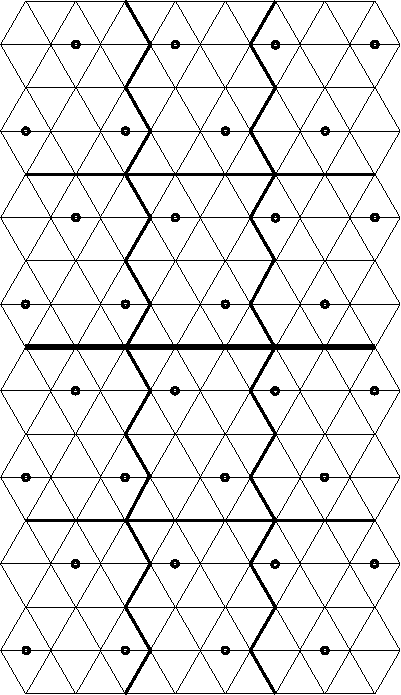
The new method is similar to what other people have been doing, and I don't know why I never thought of it before. The only major difference is that I need to intersect 3 pieces of wood, instead of their two (triangles, instead of squares).
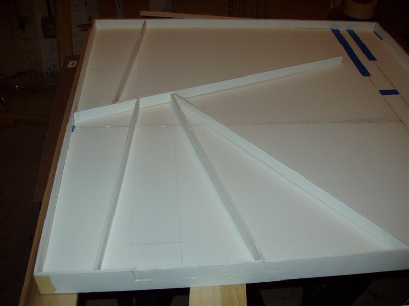
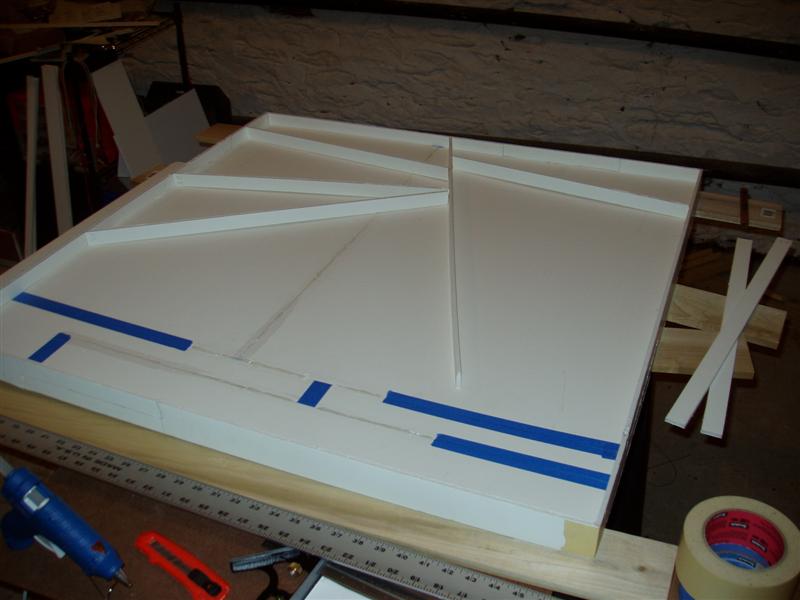
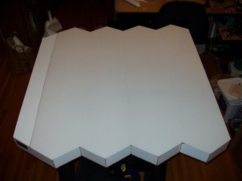
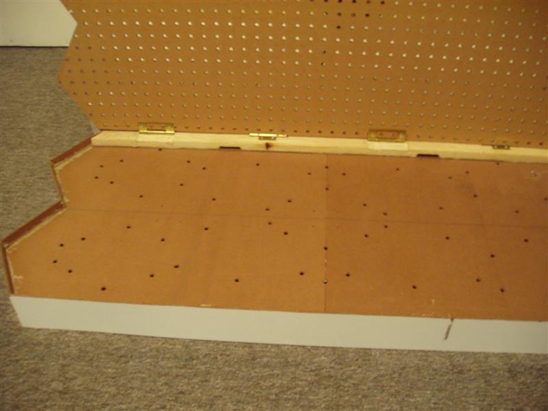
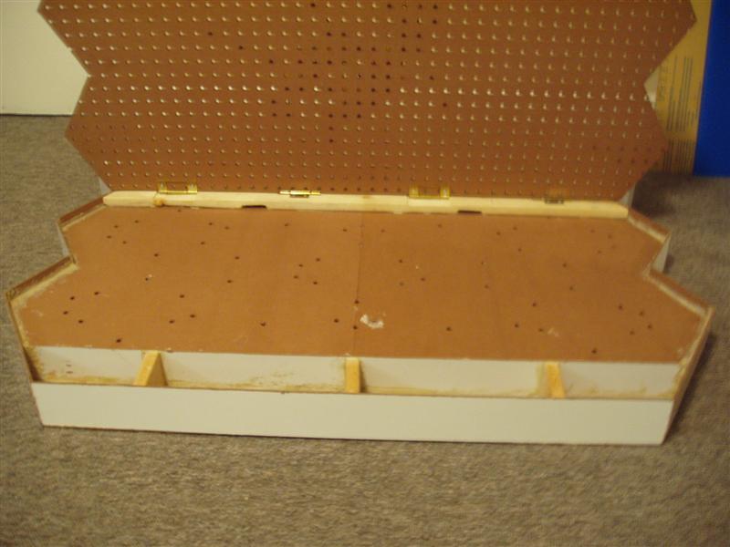
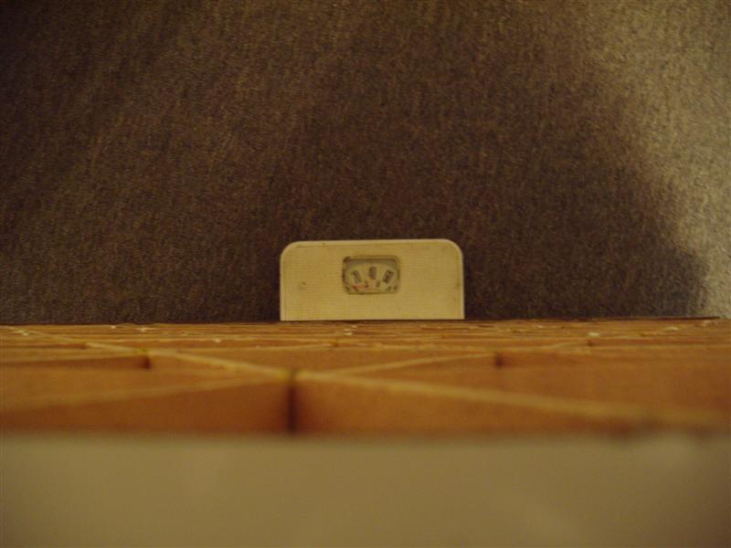
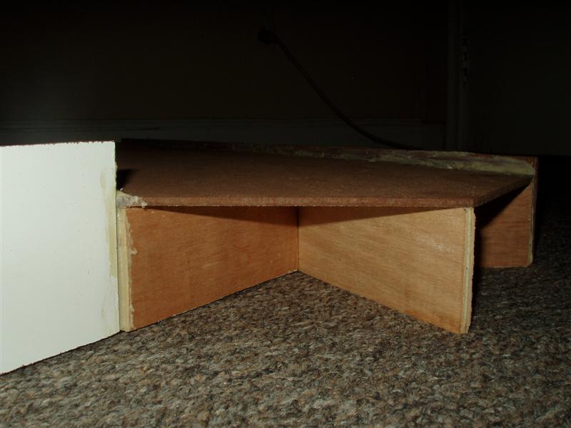
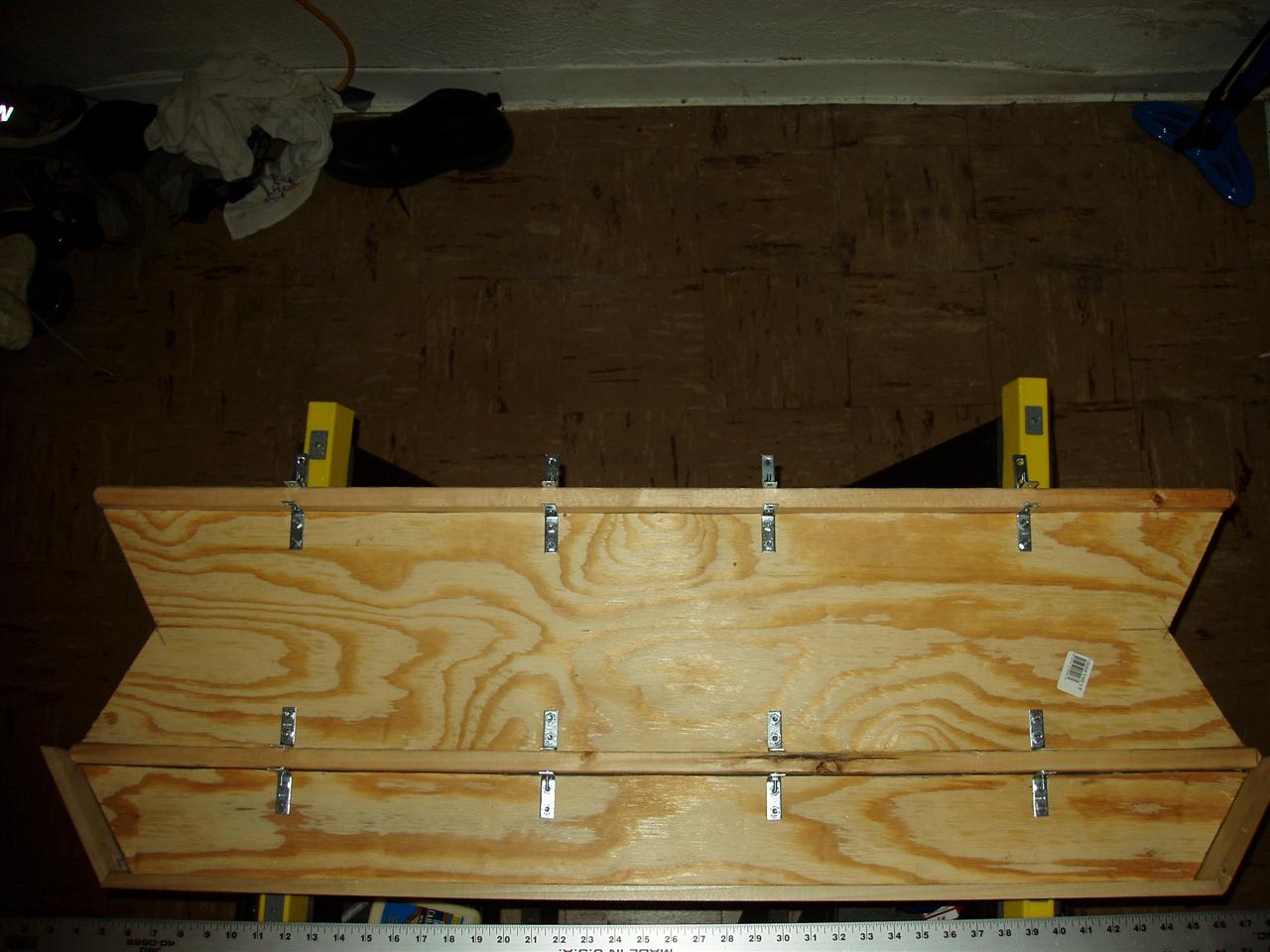
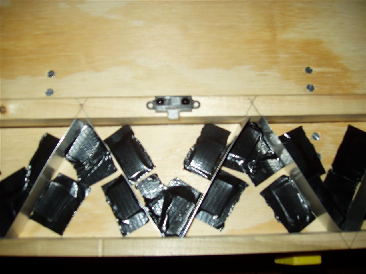
For reference, see this post and this image:


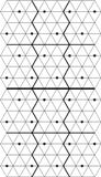
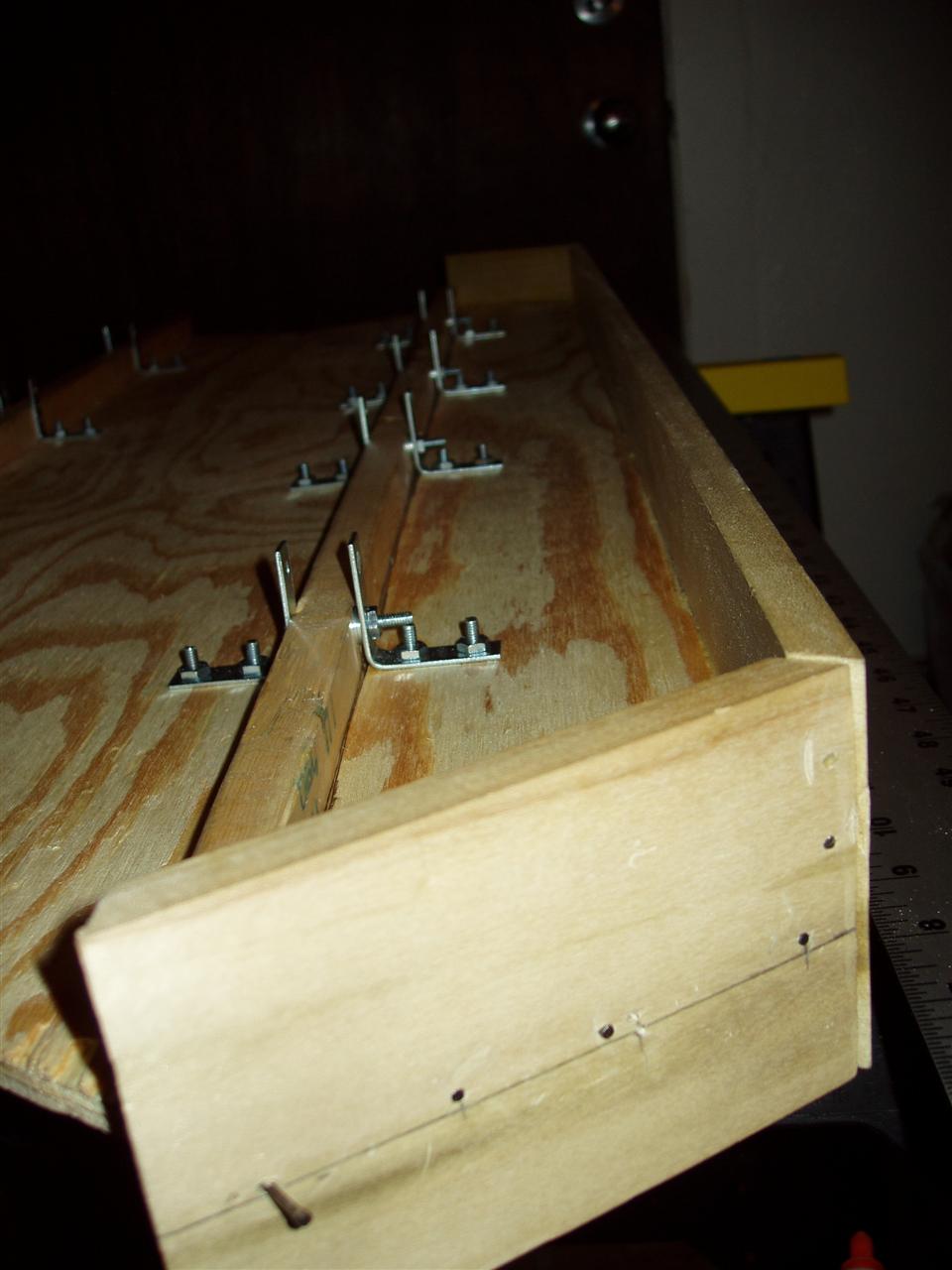
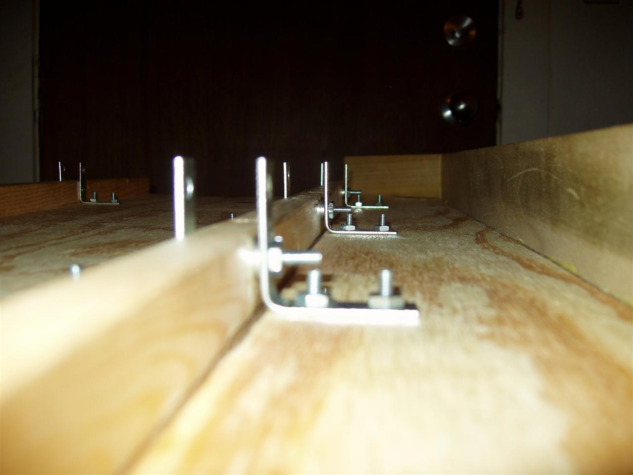
The big split between halves half-way down will still be there, but everything else will be changing. My plan is to have the pixel walls be about 2" tall (I could maybe go smaller too) and be about 1/2" thick plywood. I would use 1/4" plywood, but I need to have the outer walls be 1/2 the thickness of the inner walls. This way, I can abut any two wall sections seamlessly.
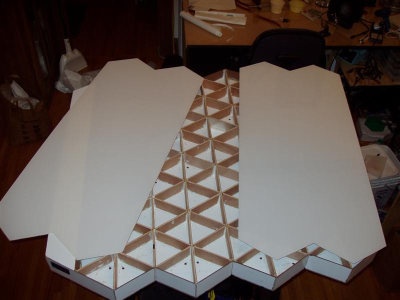
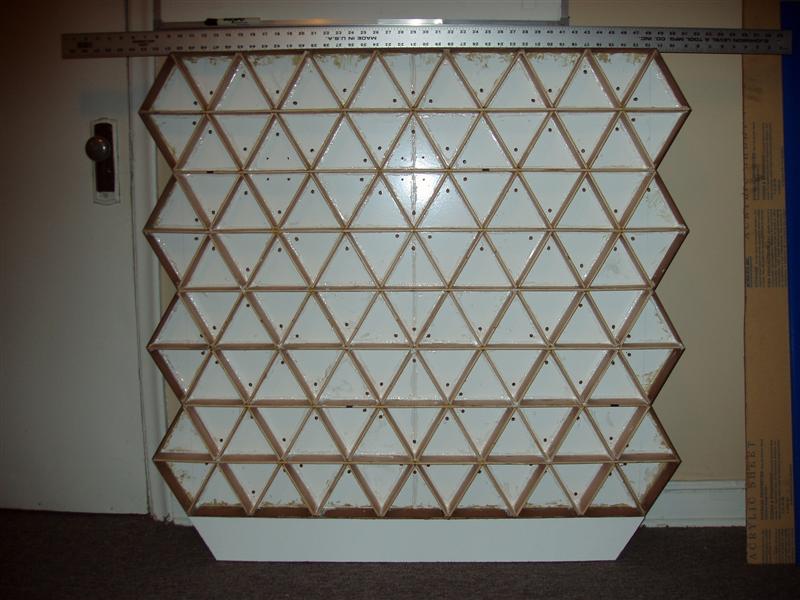
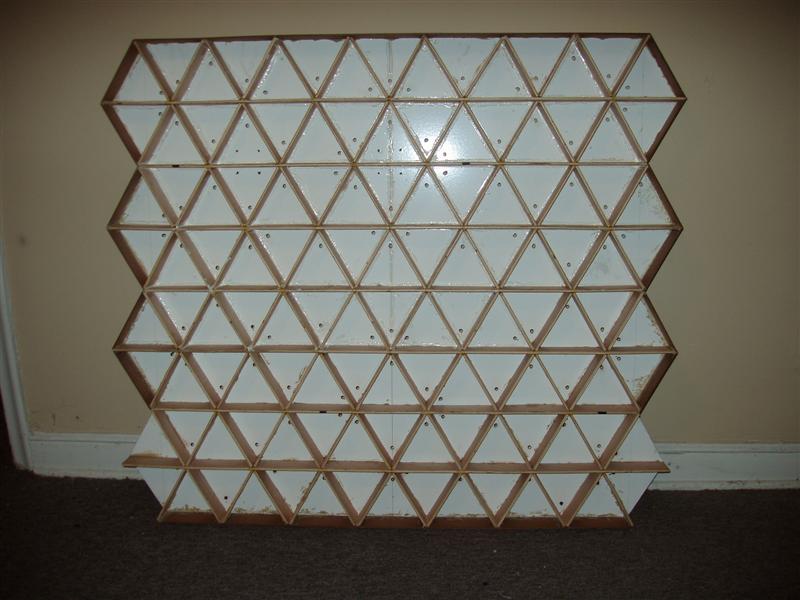
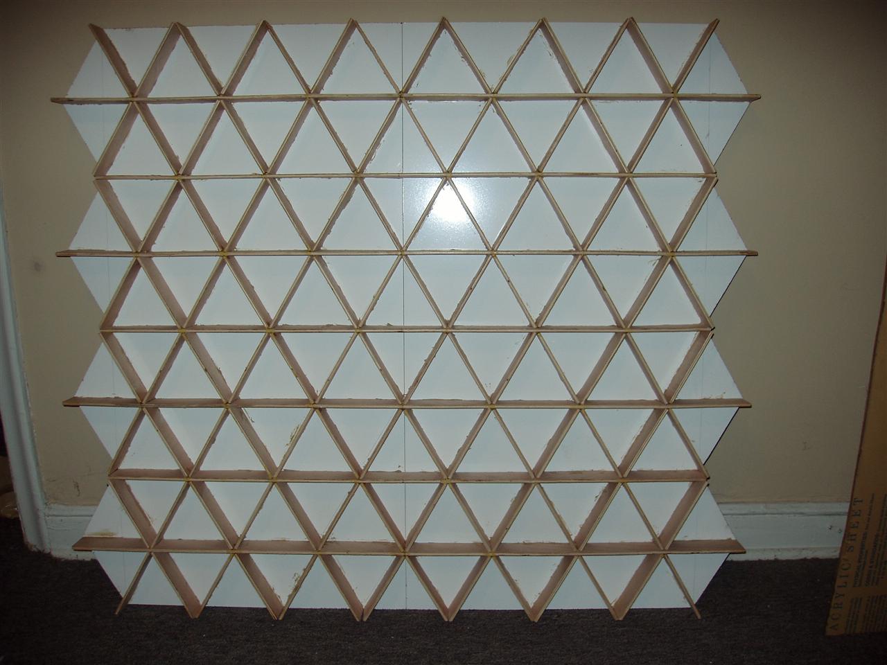
Every 5.5" (the pixel length), there will be one or two slits, depending on which axis the wood piece is, that extend a full 2/3 of the height of the wood, leaving only 1/3 (~0.66") of the wood remaining for structural integrity. The three axes of wood lengths will then be slotted and glued together (I shouldn't need anything more than glue for them; they're strong even without glue). This will give me a pseudo-honeycomb (except triangles instead of hexagons).
Then I can just affix a piece of plywood to the bottom (the thinner, the better) and I basically have the entire enclosure (minus the acrylic top, of course). On the outer walls, I was planning on using 1/4"-thick plywood, like I said, but it would be 3" tall, instead of 2". This would give me a subfloor with which I can mount the electronics and run the wiring. Since I won't be having any border around the wall, I need everything completely self-contained.

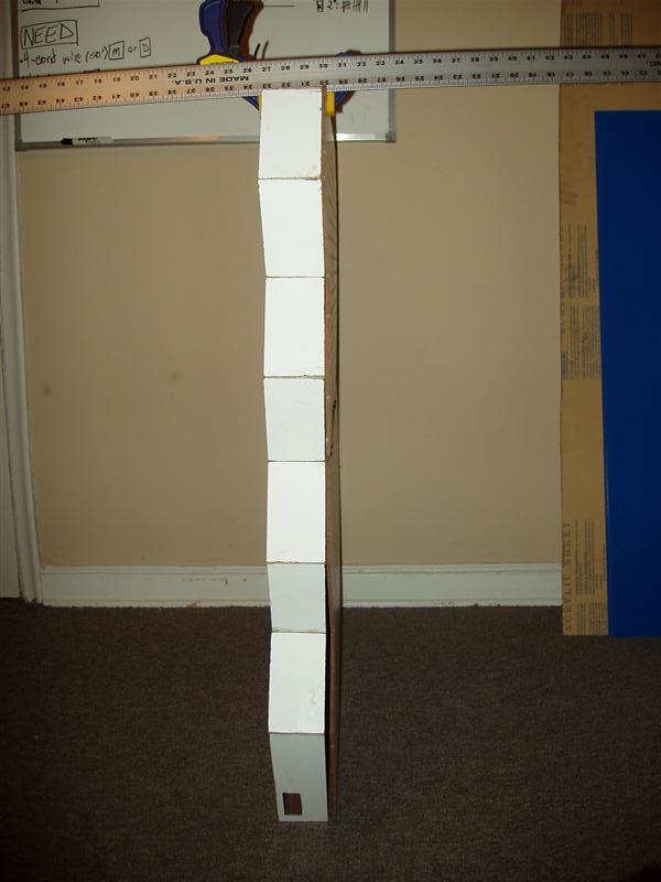
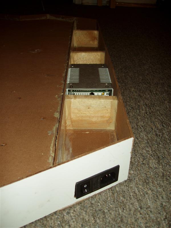
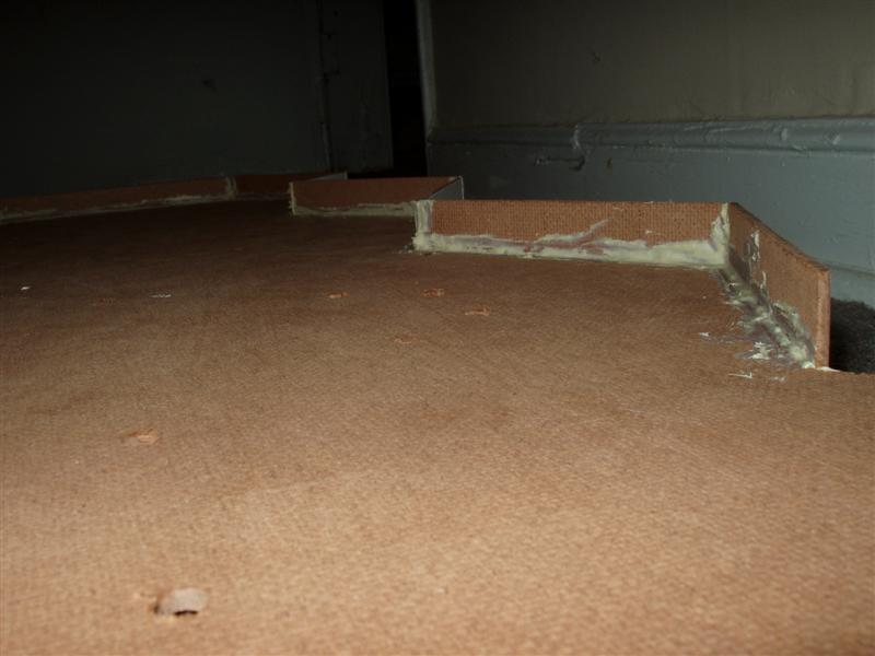
Well, almost completely. There's still the issue of the power supply. It's a full 2"x3.75"x5.8". Which means that I could mount it in an enclosure that hangs down an extra ~4" on the bottom of the bottom wall "module".

I should be able to have all of the connectors between the bottom and top modules (USB, power, SPI, and switches), as well as connectors for modules to the left and right of each of them, flush with the edge of the wall. The 1" margin on the bottom will be enough for this.
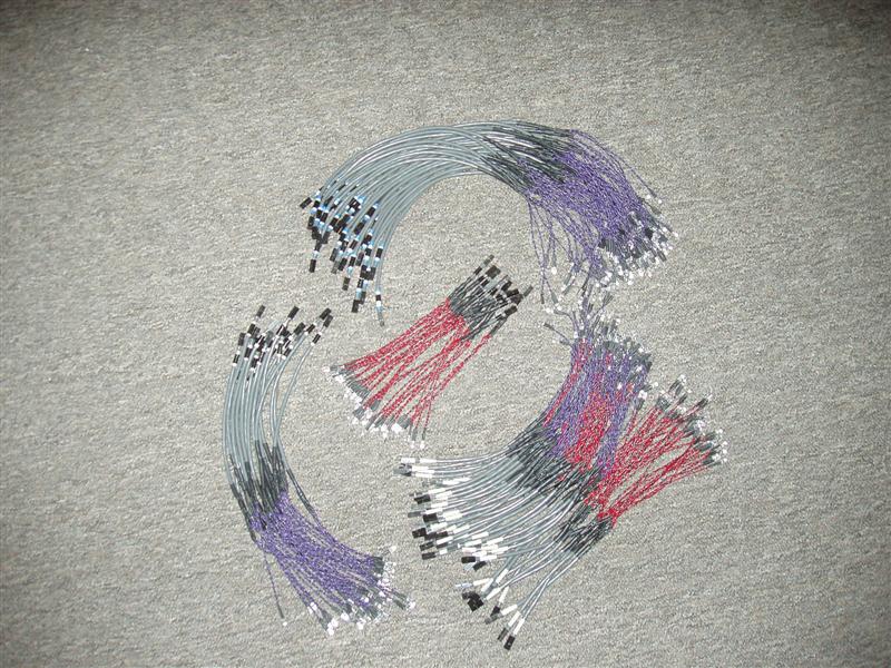

Updates
I spent a whopping $18 on 70 feet of heat shrink tubing and 100' of 2-conductor 26ga. wire at Ax-Man today. I figured I should spend as little as possible for just testing. I got maily 1/8" tubing, with some 3/16" as well. The 1/8" is a little too big for what I need and it was as small as they had, so if I were to get more, I would get 1/16" or 3/32", depending on what suppliers had available. The wire worked decently and I finally figured out a way to solder the wires to the resistors and LEDs. The only problem is that it took a moderate amount of time, so I have a long way to go. I now have one LED triplet done (yay 0.4% completed!) and I've verified that it works. It's just over 19" long, so it should be long enough to go from the board to the furthest-away pixel. That's one nice thing about having separate driver boards; I can have the boards centered around the pixels they're powering and not have to deal with LED wiring that're several feet long.

Tomorrow, I must go buy lots of wood and start cutting. I will have to come up with a way to make 4'-long cuts in plywood with a jigsaw go fast and straight. I have 54 2"-tall pieces to cut and 36 3"-tall pieces to cut. Fun, fun!

Labels: ,

Wednesday, March 15, 2006

Potential changes

I was thinking about the construction as I laid in bed last night. I may end up ditching all the construction work I've done so far. I can't really do any testing until the weekend, but I'll keep you posted.

Also, I'm in a sort of quandry about the computer side of the coding. I have no idea where to start to be able to communicate with the microcontrollers, outside of using the programming software (not really an option). If anyone has any ideas about how to go about using USB interface libraries (in C, C++, C#, Java, Python, whatever...), please let me know.

Labels: ,

Construction Progress

Construction
I've made pretty decent progress over the last week with construction of the wall. I am now up to 7 pieces attached: 3 outer walls, 2 inner floors, and 2 inner walls. Things are starting to finally come together. I've got a decent system for attaching the pieces together, even though right now it seems sorta flimsy. I think that once I start attaching the outer wall pieces (the smallish zig-zag pieces that are 5.5" long), the inner floor and walls will stiffen up.

Just in case it doesn't start firming up, I came up with a way to hopefully stabilize everything.
In these pictures:


You can see that the inner walls are attached to the inner floor pieces using angle brackets. The amount of wood sticking out on the bottom of the inner walls is such that I can only use one of the holes of the brackets, leaving another one just sitting there. I've been lining up these brackets for the last 4 mounted (as you can see in the top picture). What I have planned is using a 3' threaded rod through each set of brackets (4 threaded rods per wall section, 2 wall sections total) and then using screws on either side of the bracket pairs to adjust their positions if needed.

More pictures!
Top-down view of the top side:


Side views:


I had been playing around with different ideas for attaching the aluminum flashing to the wall. What I had initially decided on was to cut one large piece that zig-zagged all the way across a given pixel row (essentially being 4.4"x14, which is 61.6" long) and then attach it using carpet tacks. I was very leary about the first and eventually abandoned the idea yesterday in favor of doing single 4.4" long pieces (14 of them of course). I still had an uneasy feeling about using the carpet tacks to attach them to the wood. I initially tried using wood glue, but that failed miserably.
I was getting ready to go about using the carpet tacks, even taping down the pieces with duct tape when it dawned on me. I had this fear of using duct tape in the final version of it, for absolutely no reason. The pixels were going to be filled with aluminum foil anyway, so what would a little duct tape hurt? It turned out pretty well, as you can see from the pictures below, and was a helluva lot easier, less error-prone, and more error-recoverable (if I screwed up with the carpet tacks, then I end up with a bunch of small holes in the plywood) than using the carpet tacks.

Close-up of the pixels with aluminum flashing for pixel dividers, affixed with duct tape (The pencil marks are how the actual pixel divisions end up):


Distance sensor:


I decided to pull out the distance sensor just to see how it fit with the inner walls. My idea is to cut out a recess in the inner walls for the sensors, so that they end up flush with the top of the wall, like everything else. The connector will stick into a pixel a little bit, but I don't think it'll be anything major.

Labels:

Friday, March 10, 2006

Construction and Testing

Construction
I now have 3 pieces of wood attached to each other. These are the real-deal pieces and I've taken great care in aligning them and making sure that all the nail holes are correct before doing it. I used wood glue along the floor plywood and outer wall joint as nails really aren't enough. On the inner wall connection, I've only used 4 L-brackets without any glue, as I need these sections to be able to be disassembled (for now). At this point, I just need to start cutting more floor plywood pieces so I can continue.

Testing
I've done a bit more testing on my soldered uC board tonight. I soldered on the reset switch, ISP switch, and USB unload switch and verified that Windows can recognize it when I perform the correct switch incantation ritual. The uC programming software correctly connects to it and I've successfully programmed code to the device. Whee, yet another hurdle checked off.

I also extended the LED blinking program (BLINKY) to send signals to all 32 I/O ports available (the P4.1 & P4.2 are used solely for the TWI) and verified with LEDs that they all work. So far, so good.

The only major things I haven't tested yet are the ADCs. I have a bunch more to do, like get the TWI working with the driver boards, so I have a bit of testing yet to do before I get to that stage. As a simple test of the ADCs, what I've envisioned is just hooking up LEDs to each I/O port and then have it be a 32-position bar chart, displaying the values returned by the ADC. I can then test this on each of the channels of both chips (there are 8 channels per chip).

Progress marches on!

Labels: ,

Saturday, February 25, 2006

Pixel row test setup

Over the last week (and mainly just today), I've been trying out some methods of creating the internal divisions between the pixels in a given row. I already built a single 15-pixel row earlier to start things off, so I've been using that as my test vehicle.

I bought some flashing from Home Depot to do the separators (as I stated in the previous post) and cut a 2' strip. I then cut it in thirds lengthwise, giving me 3 pieces 2' by slightly less than 2".
I screwed up the first piece pretty early, as expected, and then actually thought ahead about how to cut the 2nd strip before actually cutting it.
The second strip worked out well, except I couldn't measure correctly and ended up with a zig-zag piece in which every straight length was 1/4" too short. I also had a hard time actually attaching the metal to the plywood. The nails (carpet tacks, actually) I bought are absolutely tiny and the only way I could pound them in is by using a needlenose pliars to hold them. The hammer head barely fit into the box and I kept hitting the flashing with it too. And on top of all of that, the plywood just absorbed all of the force of the hammer because it was being suspended by the walls.
The 3rd strip actually worked out well. The 2' piece I had cut ended up being about 2" too short for what I needed, but that was fine as I really didn't need to test a whole 5 pixels or anything. I used a 1/16" drill bit and pre-drilled into the flashing and a small amount into the plywood to use as a pilot hole. Then I used a (very) small amount of wood glue on each carpet tack and just pushed it in with a pliars instead of with the hammer. This worked considerably better than my first approach. I need to pick up a punch though, because the pliars can only push so hard and I need to get the nail/tack more flush than it currently is.

I just used my LED tester to wire up RGB LED's, mainly because it was a lot easier than any other method. The red was overpowering the green and blue so much (with all 3 at 10mA) that I dropped the red down to 5mA. This worked out surprisingly well.

I also experimented with the 1" border between each of the pixels, just to make sure that everything still jibed with my earlier design work. I used black duct tape (I couldn't find my electrical tape) and lined everything up properly. I think it looks pretty decent.

Here are some pictures of the whole thing:
Test pixel row, with 1 pixel lit up white:


The guts of the row, with the pixel on still:


3 of the pixels, close up, with carpet tacks visible:


Pixel mask with 1" borders (the only border that is 1" is the common section between the two; Using an incandescent lightbulb for backlighting):

Labels: ,

Saturday, February 04, 2006

Whoah!

Holy oh-my-gosh! He actually updated something!!!

Yes, lo and behold, I have actually started working on this thing again. I spent about 2 hours (I know, not a whole lot of time) doing some woodwork for the framing of the wall. I made some decent progress, especially considering there hasn't been any for about 5 months.

I had decided way-back-when that the 3" high outside wall boards I had purchased just weren't going to cut the mustard and bought a whole bunch of 4" high pieces. I spent all of my time today cutting the 4" pieces to match and replace all the 3" pieces I already had cut.
Then I started assembling an entire pixel row (in total, consisting of 3 outside pieces, 1 inside piece, and 1 floor piece). It's not the best construction, but I tried some things out and figure out what will and won't work. I used small brads to nail the outside pieces to the floor piece (seeing as the floor piece is plywood and not thick at all). This only worked "OK", as the plywood split very easily. I may have to find another method of attaching them all together.
For attaching the internal board to the floor board, I used 4 angle brackets. Perhaps it's a little overkill, but at this point, it's all just testing anyway. The end product isn't horrible and makes me feel like I've actually accomplished something, rather than just cutting random pieces of wood.

Stay tuned!! Please!!

Labels:

Thursday, June 30, 2005

Assemblyline production (part deux)

LED Driver Boards

I must be getting better and more efficient at this soldering business.

It took me 3 hours to do boards #2 & #3 on Monday night. But by the end of board #3, my brain was kinda fried and I ended up soldering 2 of the headers on the wrong side of the chip before I realized it. It wasn't a big deal because they're just the headers for the LEDs, but it was still a screw-up.
Last night I decided to eschew the cross-pin resistance checking. I figured that it was just wasting time and probably making the solder connections worse in the end. Any sort of resistance was probably being caused by the flux and not because the solder between pins was "getting too close" to each other. I also decided to move towards a more-assemblyline approach and did 5 boards at once.

In total, it took me a shade over 3 hours to do all 5 boards.
On the top side, I spent 50 minutes doing all 10 driver chips, which included everything from fluxing the pads to doing connectivity testing and pin short testing. This comes out to being 12.5 seconds per pin. Not too shabby.
The bottom side faired even better for speed. It took me only 30 minutes to do all 10 driver chips. This comes out to be 7.5 seconds per pin, or 8 pins per minute. Basically, it was taking me about 1.5 minutes to place, align, and solder the chip, and another 1.5 minutes to test it.
Of the 480 driver chip pins that I soldered last night, there was only 1 pin that wasn't soldered correctly the first time and none of the pins were shorted. Yippie me!

I can't do any more boards at the moment because I've run out of driver chips. My initial order was only for 40 and I've used a few here-and-there for testing previously. So I need to order a few more of those before I can continue.


Wall Construction

I only spent a little bit of time on Tuesday cutting wood, but I basically doubled the amount that I had before and started on 6 more internal pieces. I realized that I need a lot more 1/2"x3" pieces and that the way I was cutting the small 5.5" pieces wasn't the way that the majority of them would need to be. Luckily, I only cut 4 of them this way (I need either 8 or 16 of them)... Wood is cheap anyway, so it wouldn't have been much of an issue either way.


Planning

I'll have to really dig into designing the microcontroller board now. I'm going to run out of stuff to do with the two current projects relatively soon, so I need to work on the other areas as well. I also need to decide on LED's. I still haven't purchased any large amounts of them or the resistors to go with them. I need to get a power cord for my power supply too, so I can test the LED's with the correct voltage.

Labels: , ,

Monday, June 27, 2005

Assemblyline starting

LED Driver Boards

I got my 60 driver boards on Friday, and boy do they look sweet:


I soldered up 1 of the boards on Friday night... It "only" took me about 3 hours to do it from start to finish, so hopefully I can find some ways to speed that process up. I was having some problems soldering the 3rd driver chip to the board. No matter what I did, it always seemed to screw up the cross-pin resistance (i.e. make the resistance smaller). I was really worried about losing the first board (kinda makes it a bummer to have the very first board not work), so I went and grabbed a bottle of hydrogen peroxide and a cue tip and completely went over all the contacts with it. There was a lot of "slag" on the pins and I couldn't seem to get rid of it... The H2O2 fixed that problem wonderfully.
In the end, I managed to get >1MOhm between every single adjacent pin pair. The entire first chip I did was >10MOhm... far exceeding my initial expectations. All of these measurements were taken directly after soldering the connections too. I will be going over the whole board with 99% isopropyl alcohol (hydrogen peroxide you get from the store is generally 70% at most) and then baking the chips at ~250F for about 6-12 hours. That should clear up any remaining issues with cross-pin resistance.


Wall Construction

I also stopped by Home Depot and picked up a bunch of wood and some tools to work with. My apartment isn't all that big and I don't really have any really-available working space, so I converted my kitchen into a woodshop. For the size and quantity I'm dealing with on this project, it's not too big of an issue.
For the exterior walls, I bought some 1/2"x3" planks. They were sorta spendy ($3.50 per 4') but I only need about 22' of it, so it's not all that bad. For the internal walls, I bought some 1"x3" planks. These were much cheaper; on the order of $1.50 per 8', and I only need 24' of them. The only internal walls that are going to be wood are the horizontal sections that have distance sensors on them (see the picture in Acrylic + Contact Paper = Super-Happy Fun Time). For all of the other internal walls, I'm going to be using some sort of thin metal (flashing?).
I only cut a few pieces on Saturday night (the top & bottom exterior pieces, an internal piece, and 2 of the zig-zag pieces on the side), just to test the feasibility of my work environment. It all seems to work OK, so that's yet another part of the project I'm able to work on.

Labels: ,