Jurek and the Amazing Techno, Colored DreamWall

Jurek and the Amazing Techno, Colored DreamWall

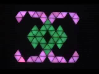
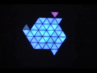
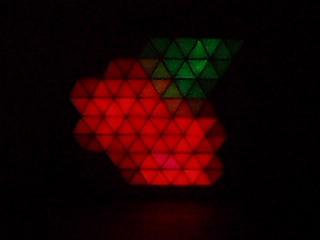
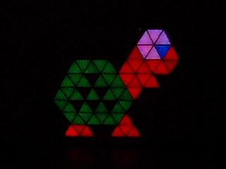
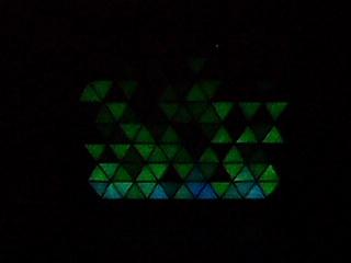
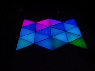
The title is mostly a placeholder, as I haven't really figured out a name for it yet. This project is a wall hanging that consists of semi-large triangular pixels using discrete RGB LED's and PWM to control intensity levels of each LED, resulting in a 4096-color display.

Friday, May 04, 2007

Center Earth

Coding update
So I suppose I can now tell you all a bit more about this project that I'm getting the Technowall (unofficial name, but it seems to be sticking).
The project is called Center Earth, and it's a pilot for a science fiction-y type show, akin to 70's shows like Doctor Who. Right now, it's slated to be used for at least one set (Can't remember the exact name of it, but it's a department in the main government/oversight building), and potentially several others.
I've been busy coding up what the director wants, and am mostly done at this point. I still need to do a bit of wiring (wiring up a pushbutton on a very long cable so he can control a trigger mechanism directly), but that's a rather minor thing. The shooting for that scene is set for a week from this coming Tuesday (so the 15th-ish). I will hopefully try to block off some time to go and supervise things, in case the code doesn't work right or certain elements of the operation need to be tweaked (changing colors, speed, etc).

Anyway, the website is here: www.center-earth.com. There's not a whole lot on there yet, but the theme music is pretty sweet, and the open call list might give you a better idea of the focus of the show.

Labels: ,

Thursday, January 18, 2007

New Space! (and fun with code)

Administrative/Logistic

Things have not been a complete stand-still in the (ugh...) 7 weeks since my last blog posting. What with the Festivus activities, cold weather, and burn-out-ness-y stuff, the last couple weeks haven't seen much activity on the wall.

However, that being said, things have happened.
Tonight, for example, I signed a lease and moved into a work space in Northeast, in the same building that the art show was in. I got me a wonderful 323 sq. ft. basement work area for all my dirty work.
I moved in my new table saw that I got for Festivus (yay), a bunch of woodworking tools, scrap wood & acrylic. I've got a lot to move in, including all my electronics stuff, and some shelving (most of which I will probably be making).
I will take and post some pictures once things look a little better.

Coding

I've also been working on some coding, in a much better sense than the C I had been working on before. I have been using Python & wx (a cross-platform graphics API akin to Tk, DirectX, or Quartz) to do a simulator/emulator/interface to the processor and wall.
Basically, I ported line-for-line the C code on the processor into Python, mainly to make sure I had to do as little debugging as possible. Once I got that working, I started refactoring the way the procedures worked, to make it more OO and maintainable.
The code isn't completely converted yet, but once I get it relatively stable, I will post what I've got for others to play around with.
I have also added one major thing I didn't have time to do (or probably EEPROM storage) for the art show: scrolling text. I made 2 different fonts, one of which only supports about 25 letters, digits, & punctuation, and the other supports the full alphabet, all 10 digits, and 10 punctuation characters. The problem with this font, however, is that the resolution of the wall only allows for about 2 characters displayed at any given time. The smaller font shows about 2.5 characters at once, as a comparison.

I'll be spending a bunch of time in the next week or two just acclimating myself and my work stuff to the new space, so expect at least a little progress!

Labels: ,

Friday, November 10, 2006

Progress Update & Videos

General

A friendly reminder that the Level_13: Bonus Round art show is opening on Friday, November 17th at 6pm! As always, there is no admission, and refreshments are provided.

Assembly

I finished mounting the switch for controlling the pseudo-random seed, on the same section as the power plug. The switch has a slightly unsmooth feel to it, but what can you expect from a $0.50 RadioShack switch?
I also removed some of the felt from the wall on the bottom half and replaced it with velcro. The bottom piece of acrylic wasn't holding up very well, so I needed some more sticking power on it. I'll probably do some more, but what I changed seems to have helped immensely.

Coding

I've made huge strides in the coding since the Sunday videos.
Things I've added:
  • 2 new still images
    1. strawberry
    2. ghost (4 color variations)
  • 2 multi-frame images
    1. Fireball is a 4-frame animation
    2. goomba is a simple 2-frame animation
  • 2 new emitters
    1. emitter_single - colors the given pixel according to a palette index value
    2. emitter_random - turns on/off (19/81% probability) a number of pixels
  • 4 new transforms
    1. triple spiral
    2. multiple spiral
    3. starburst
    4. zigzag
The new transforms all use a basic encoding scheme, so adding new ones is a relatively simple process. It's pretty simplistic and only allows me to encode 4 different actions per pixel:
  1. keep the same value
  2. get left neighbor's value
  3. get right neighbor's value
  4. get top/bottom neighbor's value
The transform map for this only takes up 30 bytes of storage (4 pixels per byte), which still leaves me with plenty of storage in reserve. If needed, I could bump this up to 60 bytes and have more complex actions, such as 2- & 4- pixel averaging (basically making the "neighbor average" function a simple map). I think currently, I'm using 602 of the 1024 available external RAM of the processor.
  • 3 channels * 120 pixels * 1 byte = 360 bytes for pixel value storage
  • 120 pixels * 1 byte = 120 bytes for temporary pixel value storage (for transform functions)
  • 16 colors * 2 bytes = 32 bytes for color palette value storage
  • 120 pixels * 4 bits for index value = 60 bytes for image map storage
  • 120 pixels * 2 bits for transform mode = 30 bytes for transform map storage
  • -----------------------------------------------------------
  • 602 bytes of external RAM storage, leaving me 422 bytes left to use!

So... on to the goods...

One of my coworkers was nice enough to lend me his video camera for a couple days, so I could take some real footage of the wall in action. I've taken and encoded 2 videos. One weighs in at 2:34, and the other is 7:00 long. I've provided 2 different encoding options, .mov and .wmv.

Shorter video, 2:34
QuickTime 4.09MB
WMV 8.56MB


Longer video, 7:00
QuickTime 46.7MB
WMV 24.7MB

Labels: ,

Sunday, November 05, 2006

Eyecandy

Assembly

I got a few more switches for the fan and the pseudo-random number generator seeder, got them mounted (I still need to mount the pseudo-RNG switch somewhere), and gosome felt glued to the back side of the pegboard. This last part was an attempt to protect the boards somewhat from the outside elements. It should stop small stray debris, small amounts of liquid, and thin metal rods (e.g. screwdrivers) from coming in direct contact with any of the boards or the terminal strips.

I also bought some hanging brackets and started working on a way to secure the pegboard to the wall. Currently, I'm planning on securing (Liquid Nailz) several pieces of wood on the back side and just using velcro to secure the pegboard. Some larger pieces of wood and a few holes cut into the pegboard should be sufficient to mount the hanging brackets, in case I want to bring it up off the floor at all.

Coding

This is the real reason for the post, however.
Behold, lots of eyecandy!


4.1MB QT4.0MB QT


4.0MB QT4.0MB QT


I'm sorry about the short videos; my camera can only take up to 16 seconds at a time.

These videos show the 6 still images I've designed (from this directory), as well as the single generator I've got coded up (edge emitter). Also shown are several of the transforms in action.
For the still images, it picks between two different transforms:
  • fade
  • neighbor average
Fade works like I described in my previous posting: simply fading from the current color to either black or white (exclusively black in these videos).
Neighbor average takes the value of each pixel plus the 3 adjacent pixels, and averages them to compute the pixel's value. Over time, the whole board turns to black because there is a certain amount of information lost with each average computation that takes place.

For the edge emitter, there are two transforms that are being used at the same time:
  • fade
  • translate
Both work as I described before, and the translate always works in the direction opposite where the emitter is positioned; if it's generating pixels on the left, the translation happens to the right.

Right now, I'm using about 5.2kB of codespace. Each of the still images takes up a moderate amount of space (~600-800 bytes), so I can't have a huge amount of them. However, I'm still well under the 32kB of available space.

The bigger issue currently is speed. The neighbor average function is very expensive, mainly because I have to keep an equal-sized pixel map to calculate the new values and then copy the new pixel map over to the old one.

Labels: ,

Sunday, October 22, 2006

Mondo Update

LED Segments

I've gotten 20 more of these done! That puts me at 152/240, with 2 more needed for this first module. I will probably do them a little tonight and then finish them up Monday or Tuesday. After that, I can stop for a while (thankfully). My fingers are pretty sore and sensitive from the heat and metal.

Assembly

I had to remove one of the pieces of contact paper from one of the pieces of acrylic, because the velcro I had been using just wasn't cutting it (or, more precisely, was burning it from the hot glue). I bought about 30ft of self-adhesive velcro, 3/4" thick, and used a fabric cutting wheel to make nice, straight cuts along it (gotta cut it into thirds!). This works wonderfully, as the adhesive on the velcro is unlike anything I've ever seen. It stick amazingly well to basically everything.
Anyway, I got a new piece of contact paper put on the acrylic and spent a couple hours today putting the velcro on it. The first (bottom) piece of acrylic is now completely done and looks "OK". I say "OK" because there are still air bubbles randomly throughout it and a few minor holes. Not the best job in the world, but I'm now under a small time constraint (read below).

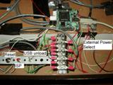
I finally got the processor board mounted to the wall, along with the different switches for reset, ISP, USB unload, and power supply selector. The only switch I have yet to mount is the main on/off switch. The switch I've been using isn't the one that I plan on using, so I haven't made a hole for it yet. Actually, I'm not sure if I will even use a switch right away. It's not entirely needed (the main power switch works fine) and especially not right away.

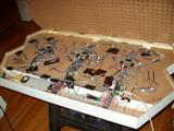
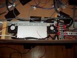
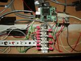
Here're some pictures of the guts behind the pixels (and man is it messy!):
InternalsPower SupplyProcessor MountProcessor Mount, with labelled switches


There're still plenty of wires to add, such as power & control cables for the "upper" 3 boards, as well as finalizing the cabling for everything. You can see in the overhead shot that there are orange, purple, and grey clip cables attached to random squiggly wires. These are the reset lines for the boards, and I'm going to be tying them to power directly, but I don't want to route the cables completely yet. Once I get all 6 driver boards working, then I will finish that step.


The processor and switches are mounted on the opposite side as the power supply, with enough room to take up the two remaining compartments (the angled compartment on the end is barely used).

You can also see the two fans (poorly) mounted for cooling. The one on the right blows into the area, whilst the one on the left blows out of it. They probably don't work too well, considering that there are large open areas for the air to simply escape through, instead of cycling the hot air around the power supply. I'm still not entirely sure how much cooling will be needed. I started doing some temperature measurements without the fans running, but the battery for my multimeter died, so I couldn't test any more. After about 3-4 hours of running 1/2 of the pixels in just 1 module at about 20% capacity, it rose from 74F to about 95F. Once I get everything running, I'll try turning all 120 pixels of module 1 on full white and just leave it there for a couple hours. If all goes well, it shouldn't get much above, say, 130F, which is still fine as far as I'm concerned.


I cut a small notch in the internal wall for the power supply source switch, which fit nice and snug in there. It's currently only being held in by duct tape (I don't think "duct tape" is even used by HVAC technicians on ductwork), but that can be "enahanced" with glue later. The other 3 main switches are all mounted on a simple strip of galvanized hanger strap. The large holes worked perfectly for the threading, and it's stable enough for what I need.
The large terminal block looks very similar to the one next to the power supply (which is used for power!), but is for the TWI bus. This seemed like the most effective method of breaking out the bus from the processor to the 6 boards that all require the same signal.

Coding

I've begun coding up a few basic tranform functions to apply to the wall. Currently I have:
  • Inversion (inverts the colors of all the pixels... red -> cyan, black -> white, yellow -> blue, etc)
  • Shift up/down/left/right (shifts all pixels up/down/left/right 1 row)
The inversion can be enhanced to only invert certain channels (e.g. only the red channel)
The shifting functions can either roll over the shifted-out pixels, or just shift in a blank (black) pixel.
If you combine "shift up" with "shift left", for example (or "shift down" with "shift right"), then you get a tranform that shifts all pixels along the upper-left/lower-right axis (there are 3 axes with triangles, not the normal 2 with rectangular ones!). Likewise, combining "shift up" with "shift right" (or "shift down" with "shift left") translates the pixels along the upper-right/lower-left axis.
Simple, but powerful stuff.

Other potential transform functions are
  • Average (averages the surrounding 3 or 12 surrounding triangles)
  • Rotate (rotates the pixels 60 or 120 degrees about a given pixel)
  • Fade (slowly fades the pixel from its current value to black (or white, or any given channel!))

I managed to find, in the documentation, the status bits for controlling the speed of the TWI bus. I think, by default, the transmission speed is set to 62.5 kHz. By setting the speed bits to the fastest setting (266.6 kHz, a 4.3x speed increase), I was able to increase the framerate of the wall by about 50%. This was a very welcome change, indeed. Hoo-ray!


Announcement

Some of you may have been wondering why there has been a huge bump in the progress in this project over the last 2 months. Indeed, I've put in 27 hours this previous week, and 85 hours since September 1st. Well, there is reason for this, and quite an exciting one (for me, at least).

Now that it's official, and I've committed myself time-wise for it, I feel I can mention that the "technowall" (NOT the official name!) will be part of the upcoming (Artist's reception/opening is on November 17th) video game art show at Altered Esthetics: "Level_13: Bonus Round!". Their address at the time of the show is:

Altered Esthetics
1224 Quincy St. NE
Minneapolis, MN 55413

This is just off Broadway and Central; for those that need directions, please consult your favorite mapping website. If you need more information than this, please contact me.

I will only have the 1st module done, and won't have any computer interface ready, but I will be spending a fair amount of time with coding to get various random (and not-so-random!) patterns working. The pseudorandom seed switch (see the October 10th post) should keep everything random enough for my needs.

I have already designed several patterns, as well as a few other neat designs, with more to come (hopefully). If anyone wants to try their hand at designing something, here is a PNG template that I've been using:
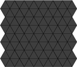

Please email any creations to me! I'd love to see people's creativity with such a small (and oddly-constrained) resolution!

Exciting news!

Labels: , , ,

Thursday, October 12, 2006

Gluing progress

Assembly
20 more pixels glued into place. That leaves me 33% done with the gluing. This round went much faster than the first time. Woo!

Coding
I've just been playing around a little bit with things here and there. Currently, there's not a whole lot I've been really attempting. I would like to have some sort of unique pseudo-random number generator. Pseudo-random is fine for what I need, but that's only as random as its initial seed, which is deterministic for the microprocessor without any sort of analog input (white noise, ADC, user input, etc). I think the easiest approach currently would be to have a small switch on one of the unused ports that can be pressed at any time while it's running that would update the seed. I could just have an unsigned int as a counter for the main loop, and whenever it detects the switch as closed, I can just call srand with the counter as an argument.

Parts
I'm going to be ordering a few odds and ends (wire, terminal blocks, crimp terminals) for the current stages I'm in.
I've recalculated a few times how many of each length of LED triplets I will need, and with my current calculations, I need to solder 31 more triplets of various lengths (2 10", 17 8", & 12 4") for the first module.

Labels: , ,

Tuesday, October 10, 2006

Coding
Wow, I've had a productive (and depressing and exhausting) last 3 days. This post is long, so please bear with me. It is entirely about coding, so I don't blame you if your eyes gloss over and you stop reading it because of boredom.

ADC
I set out on Sunday to try to get the ADC and distance sensor working correctly. The distance sensor was fairly easy to hook up and seemed to work fine. 0.4v to 2.1v, depending on how close something was (higher = closer). I wasn't really worried about that, however.
The ADC was of prime concern, and it seems that my concern wasn't without merrit. I was eventually able to get the code to write to the ADC, as well as read at least 1 byte from the ADC (all my TWI programming thus far has been purely writing). I only think I am able to read a single byte, as I'll explain in a bit.
Try as I might, I wasn't able to get anything usable from the ADC off the TWI bus. I could only seem to get the first 4 bits. It's a 12-bit ADC and thus requires 2 read cycles on the TWI to get all 12 bits. The first 4 bits are the MSB and generally the most important. The final 8 bits in the 2nd read cycle are the LSB's and still important. It seems like the only thing I have been able to get from it was all 1's (not promising, it means the ADC is flatlined somehow).

After a couple hours of poring over whitepapers and fiddling with code and a multimeter, I eventually found some bad news. The power being supplied to the ADC's is about 4.1v. The nominal voltage listed in the datasheet is 2.7v-3.6v (I assumed my voltage regulator would correctly drop the 5v coming into the board down to 3.3v). However, I failed to read the part that said that if the voltage is above 2.7v (NOTE: "above 2.7v" doesn't mean "above the nominal voltage range"), then the REF pin needs to be tied to VDD instead of ground, as it shows in the handy little wiring diagram (which is the way I have it wired up on the board).
So it looks like the ADC's on the board are bunk. I think they are functioning fine, but they don't have the correct voltage reference to properly do the ADC conversion.
It looks like I'll have to wait for version 1.1 of the microcontroller board to do any sensors. :( Boo-hoo! (unless I can rig up some other board with different parts).

Compiler
My next major hurdle was something that has been lingering with the code since day 1. I have been using Keil's uVision development suite for the 8051 microprocessor. The starter kits came with an evaluation version of this software, which is fully functional except that you can't compile code larger than 2k bytes. I had been hovering at just under 2000 bytes up until I started testing the ADC, but then noticed that I had to start removing unused variables because I was hitting the limit. I looked into pricing for the software, but was immediately floored at the $1700 pricetag. I found a newer version of the software (as an evaluation version as well) and inquired about whether or not they had a "light" or "hobbyist" version. Of course, no go there. $1700. Take it or leave it. Well, I certainly chose the latter option.

After some quick searching, I found many different options for 8051 compilers, both freeware, cheap, and full-priced (with evaluation versions). I tried them all. Some several times. Some of them had really horrible C compiler support ("bit" wasn't a typedef, incomplete SFR's (Special Function Register), etc). Some I just couldn't get to work (horrible UI, DOS-based IDE???, goofy compiling steps).
My most-promising candidate was SDCC. It's an open-source retargetable compiler for various microprocessors. It supports Intel 8051, Zilog Z80 (TI-85 I think and GameBoy), Motorola 68HC08 (precursor to the 68HC12 line), and Microchip PIC16 & PIC18 lines. It was able to compile the uVision code basically out of the box (I had to change a few include files, which is understandable).
Unfortunately, the first time I tried programming the hex file onto the uC, it failed. After a brief visit to the documentation, I found that the default format, .ihx, isn't compatible with most programmers and must be converted to .hex with an included converter. This I tried and again, it failed! Back and forth I went, comparing uVision .hex to SDCC .hex and trying various compiler options to no avail.
I did some searching on their message boards this morning and eventually found a post referring someone to search on 8052.com for help. Then I found this post:
Atmel has been shipping boguous header files for several "non Keil" C compilers for some years now. You're lucky if IAR throws out warnings/errors.
(The header files Atmel ships for SDCC are boguous too but the SFR definitions look like variable definitions to SDCC so you get no warning.)
Vunderbar!
So I downloaded the header file they provided (Thank the Gods!) and after some quick modifying of the SFR header, I was able to get it to compile and run in both uVision and SDCC!
Yay, the shackles of a 2k codespace have been broken!
However, with one very minor caveat, the SDCC compiled code is about 50% the speed of the uVision code. Not a big deal currently, and I don't think it will impact me too much. I have yet to dig into compiler optimizations, so there may be some speedup yet to be had.

And that is how I spent my summer vacation...

Labels:

Saturday, October 07, 2006

Pretty Colors!

Assembly
I made some more good progress today. I got 20 of the pixels glued into place (the first driver board I was testing with Thursday). This means a far better color mixing than Thursday's video had. As you can see by the first video (4.2MB), there are really very few hotspots at all and you have to look hard to find them.


The second video (3.4MB) was a request by someone who wanted to see the LEDs in action without the diffusing acrylic. It still looks pretty neat and gives a bit different of an effect. Maybe I can make 2 different tops, one that's the standard acrylic with contact paper and another that's either clear acrylic or slightly-buffed/sanded.


Coding
Yes, I actually have made a small amount of progress in the coding department today. There were a couple bugs and inconsistencies with the way I was coding everything up. I wasn't able to address a single driver chip individually, so I was seeing some rather odd side effects whenever I tried.
The main issue I tracked it down to was P0 (one of the I/O busses) not working at all on either the starter kit board, nor my own board. Perhaps there's a processor register setting that I'm not doing to get these ports to work properly; I'll have to dig through the manual.
As is evident in the videos, I am quite able to address each driver chip individually.

Miscellaneous
I also tested to see how white "white" is, and it's rather sad and abysmal. On most pixels, it's quite pink (red is overpowering), and in others, it's purple or blue (green is underpower). It's a little late in the game to fix this, so I guess I'll just have to live with it. Oh well... :/

Labels: , ,

Tuesday, April 18, 2006

Success after bug fixing

Well, I spent quite a few hours reducing code and trying to identify problem areas and in the end, I finally figured out the root of my problems.
I had a "while" loop that was supposed to be updating the data to be written out on the TWI bus each cycle, but with the mode that the driver chips were put in for 8 consecutive bytes being written, the while loop wasn't getting executed really at all. So it was basically writing the same first 1-byte register to each of the 8 1-byte registers. I had to disable, rework, and hard-code lots of sections until I figured this out, but after a quick code fix (the data to write is updated after the previous data is ACK'ed in the interrupt handler), this is now working wonderfully.

Unfortunately, there really isn't a whole lot to show yet. I was hoping to have a few nice videos for everyone of everything blinking nicely, but as it is right now, it's just a bunch of LEDs on the ends of wires. Once I get some holes drilled into the wall section, then I can actually get some pixel visualization and snazzyness.

Until then, lots of soldering left to do. I've decided that this next batch of 17 will use only a 6" piece of 4-conductor wire instead of a 12" piece. I'm still not entirely sure what lengths I'll need for where, so I'm not going to go off and make 200 triplets with 12" 4-conductor segments. So hopefully, this will give me a little bit better testing possibilities.

Labels:

Friday, April 14, 2006

Driver board success

Sorry for the lack of updates this week. Lots of stuff going on and it's nice outside.

Driver Boards
So several hours after I made Saturday's post about getting 30 LED triplets done, I finally got the driver board with 4 driver chips communicating properly with the microcontroller. There were several levels of debugging involved.
  • The first was physical. There were two or more communication wires that weren't terminated properly on one end, causing the driver board to not be getting the correct signals. Time To Fix: ~1.5-2 hours (eek)
  • The second was logical. The /RST line going into the boards was being pulled low instead of high. I thought I had hooked it up to a power pin on the microcontroller starter kit board, but I guess I had it hooked up to ground. Time To Fix: ~20 mintues?
  • The third was functional. There were a lot of coding changes that needed to be made to get the uC to talk to 4 chips serially and found several "inconsistencies" with how I was doing it before with just 2 chips.

Programming Issues
I had the TWI slave device address set to active-low, meaning that the port that was low was the active chip. In a 2-chip situation, this wasn't an issue because one was low and the other was high. This was an easy fix; just point to the correct address (0x24 instead of 0x20).

There were a lot of "issues" I thought I was having with software that ended up being the wiring issue above. This caused me to spend most of my time debugging software, trying to figure out what was wrong. In the end, I figured it out, but I had been barking up the wrong tree. As such, I had lots of fun ripping out all the debugging code.

I had been storing each LED intensity value as an unsigned int (hah!). This is 4x the amount of storage space per LED that I needed. 4 bits needed vs. 16 bits per unsigned int. I then converted it to use 1 unsigned int per pixel, leaving only 4 bits per pixel wasted (instead of 36). However, this increased the overhead to store/retrieve the value of any given LED intensity, as I now needed to go through encoder/decoder functions.

I was still having issues getting each pixel to display a random solid color. I would get one of white, green, magenta (red+blue), or black. At first, I was scratching my head as black should have never been coming up. Then I realized that the processor was only 8 bits and an int would only be 8 bits as well. After some calming (count 10... 9... 8...) and looking in the processor spec, I finally find that ints really are 16 bits wide. I spent a little bit of time using the debugger to see if red, green, and blue were getting encoded and decoded properly (it appears they are). I still am not sure why red is showing up as black and blue is showing up as red+blue (or the other way 'round). Hopefully another debugging session will fix all of this.

LED Triplets
Some small progress to the soldering fun. Not much, but 1% is 1%.

Labels:

Wednesday, March 15, 2006

Potential changes

I was thinking about the construction as I laid in bed last night. I may end up ditching all the construction work I've done so far. I can't really do any testing until the weekend, but I'll keep you posted.

Also, I'm in a sort of quandry about the computer side of the coding. I have no idea where to start to be able to communicate with the microcontrollers, outside of using the programming software (not really an option). If anyone has any ideas about how to go about using USB interface libraries (in C, C++, C#, Java, Python, whatever...), please let me know.

Labels: ,

Monday, March 06, 2006

The Good, the Bad, & the Better

Wow... what a week.

The Bad
On Sunday (the day after my previous post), I decided to pull out the microcontroller board and test out the processor. I also had plans on trying out the processors I bought for this purpose, so I didn't have to use the one that came with the starter kit as well as plans to test my newly-finished uC board.

I pull out the board, dust it off, put the processor in, and hook it up. Nothin'. Windows says it doesn't know what the hardware is and that I should unplug it and plug it back in. !*@* I play around with things for a while: I try reinstalling the software; I try a different uC; I try using a different computer. Still nothing. Ugh...

I check DigiKey to order another one. They have 1 (!!!!!) in stock, and it's for $82 instead of their normal $132. At least something's looking up. I also need to order a bunch of resistors, as I finally found a good match for mixing. 280 Ohms for red, and 69.8 Ohms for both green and blue. These values are driving red at 10mA and both green and blue at 20mA. Go figure, the red at the same mcd power is twice as powerful as green or blue. Oh well...
So I add 500 69.8 Ohm resistors and 250 280 Ohm resistors to my shopping cart (240 pixels) and I add in a few random switches to test out for the reset button, voltage source, USB unload switch, and ISP switch and off my order goes... ZOOM!!! I love 2-day ground shipping for $5.

The Good
So then Tuesday rolls around and I get my uC starter kit board #2, 750 resistors, and switches. I didn't have any time to play around with them at all Tuesday or Wednesday, so they sat awaiting my involvement until Thursday. Thursday rolls around and I pull the new starter kit out and hook it up. Wonderfully (and expectedly), it works on the first try.

OK... now what?

I take the new processor out of the new starter kit and stick it in the old starter kit. It works perfectly...
I take the old processor and put it in the new starter kit. It works perfectly...
I take the old processor and put it in the old starter kit. IT works perfectly...

AUGH!!!!!!!!!!

So my stupid self actually had the processor in wrong. I had it rotated 90 degrees and had just assumed that the package of the processor or the socket wouldn't allow me to do that. Oh well... not all is lost.
What this allows me to do now is to use the SPI (Serial Peripheral Interface) (or even the TWI for that matter) to do inter-uC communication testing. Whee, what fun! I played around a little bit and (thought I) managed to get the two processors to communicate properly. Oh what joy abounds!... almost. It turns out that that wasn't the case at all.

I had also ordered through Techni-Tool a bunch of different supplies, including a new circuitboard vise, solder reel, tip tinner, and (most-importantly) a smoke absorber. They are scheduled to arrive on Tuesday, so I can continue my soldering fun then!

The Better
OK, so Saturday, I dive back into the board and try to do more with the inter-uC communication. I turned the slave board on and noticed that the light patterns were exactly the same as I was seeing before, except this time it wasn't hooked up to the master board.
After some debugging, I found out that there is a pin on the SPI wire set (there are 6 on the starter board) that is called SS. This stands for Slave Select and is only supposed to be asserted if it is supposed to be the slave that is being communicated to. I had these hooked up to each other, so I'm sure they were just freaking out about who was the slave. Anyway, Atmel had some sample code that didn't use the SS line, so I just used that instead.

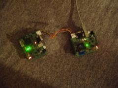
Two starter kit boards, hooked together via SPI. Note that the slave board isn't being connected via USB to anything; it's getting its power from the SPI bus.


Lit version:


Quicktime Movie (2.33MB):


I got a pretty non-random pattern to successfully be transferred from the master to the slave uC and it appears to work properly this time.


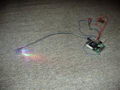
I also got a wild idea to test my as-of-yet untested uC board that I finished soldering a couple weeks ago. I reprogrammed the uC to just randomly blink the LEDs on the test board (which use Port 3 of the uC) and then dropped the uC into the test board. What followed made me very joyous and I breathed a very big sigh of relief. What this amounts to is that the board had been started 7 months ago, involved many different steps and revisions, caused me many headaches, and kept me up at night wondering if the core component would actually work. Huzzah! (No one says "Huzzah!"... sheesh...)

Picture of the setup:


Quicktime movie of the lights a-blinkin' (1.05MB):


The Caveats (special feature!):
  • For some reason, the voltage regulator is outputting at 4V instead of 3.3V, but the chips I use support up to 5.5V, so that's no biggie.
  • I haven't tested either of the ADCs on the board
  • I also haven't tested the USB data port (the computer never recognized the device when I plugged it in, so I'm sorta suspect about that)
  • Nor have I done an exhaustive test on the ports (only a few pins of Port 3)
  • I also haven't tested the current limiter on the USB port, so that may or may not work either. It wouldn't be the end of the world if that didn't work, however.
  • I still have to figure out how to solder the LEDs together on a piece of wire. The one piece I soldered together looks like crap and won't work at all. Plus, I have to do 240 of them. Fun, fun!

Labels: ,

Friday, June 03, 2005

Soldering and code update

Sorry for the delay in posting... It took me a day or two to get back into it after my vacation.

Vacation Report

Budweiser has this billboard in Times Square in Manhattan that uses triangular pixels. I didn't even know it existed until this last weekend when I noticed it there. It was on the south end of the 7th Ave/Broadway intersection, right below the Cup-o-Noodles billboard.
The triangle orientation was rotated 90 degrees compared to what I'm planning on doing and it had about 3 times as many pixels as mine (its width was about the same as the height for mine, but its height was about 3x my width... in raw pixels that is, not dimensions). Unfortunately, it was a Budweiser ad and the only colors they ever used were red, white, blue (for the flag, of course) and tan (for beer and foam, along with white). I was really hoping to see other colors from it, but alas... that was all.

When I went back to look at it at night, I noticed that each of the pixels was made up of about 50 or so smaller pixels. I couldn't tell if the subpixels were rectangular or triangular, but I'm willing to bet that they're rectangular. There were a rather large number of the subpixels that had one or more of the RGB component colors blown out. For example, magenta where it should have been white, indicating that the green component was blown. Still, it looked really awesome from a technical standpoint (I really couldn't care less about the actual content of the ad).


Soldering

I got my new soldering iron and it works wonderfully. Wednesday night, I tried it out and I was amazed at how much easier the 1/64" (about 15 mils) tip was than the 50-mil tip I had before (imagine that). I was able to solder 2 driver chips onto 2 adapters without much problem. That being said, I still have some room for improvement. The first one I soldered had WAY too much solder on it and I had to use wick across all of the pins just to pull enough out. In the end, the worst cross-pin resistance I had was in the low MOhms. The second one faired much better (although I still had too much solder) and the cross-pin resistance increased an order of magnitude. Hopefully, by the time I actually start soldering the driver chips to the board, I won't get any resistance at all.


Coding

I spent the better part of this evening working on abstracting out some common tasks on the code to deal with programmatically setting pixel values better. At this point, I can call a function when I want to set any single register on a particular driver chip and I have a decent amount of automation in place for the 8-register writing necessary for all 15 LED intensity values.

I noticed that the code I had running before was resetting the driver chip each time it was writing out the intensity values, so by removing that code from the infinite loop, I was able to speed the code up immensely.

Currently, I have 2 driver chips hooked up and I can access each of them individually and assign a color to a particular pixel with relative ease.


I think I'm ready to lay out the driver chip board (should be easy... a header or two... the driver chip... and a couple of resistors) and possibly place an order on them. Progress continues!

Labels: , ,

Wednesday, May 25, 2005

Progress Update

So it appears that my soldering job gets worse and worse with time.
I tried doing some code testing yesterday and I kept getting feedback voltage from the 4.5V (3 AA batteries) source into the microcontroller board. Very "not good".
I measured the resistance across the pins and it had dipped about 100X since Friday (down to ~4kOhms). I tried testing with the glued chip, but it was spotty at best and after a little bit, the chip accidentally stuck to my finger more than the adapter and popped completely off the adapter.

Thankfully, I have a new soldering iron coming tomorrow from Mouser (along with some more wick and 100 feet of 4-conductor wire). I already bought a 10-mil tip in my previous order from them and this is the iron that the tip goes with, so all should be well.

I settled in on a good size for the board. 15 pixels wide and 16 pixels high. At 5.5" on a side for the pixels, this makes the wall 3'8" wide and 6'4" high. Seems like a good size to me. A rough estimate of divider material (e.g. wood) needed is 175.5 feet. Youch. That comes out to be 48 4' pieces of wood. No only is that a lot of wood, it's a lot of weight. The outside shell should probably be wood, but the internal dividers don't necessarily need to be. I'm open to suggestions for materials, if anyone has any. It doesn't need to be super-thin (max of maybe 1" wide) and the only real requirements are that it must be opaque and must be drillable or glueable.

I spent a little bit of time fixing up the code and putting in some basic structure to deal with selecting different driver chips. Since I don't really have a good setup for testing the driver chips any more, I can only really compile it to make sure THAT works. I set up a function to deal with the 2-byte transfer method (1 address + 1 data) over TWI. I still have to make one that sends 9 bytes (1 address + 8 data) to control the LED intensity values. Just doing that really cleaned stuff up and made it so much more readable.

There won't be any more blog updates until Tuesday at the absolute earliest (most-likely Wednesday). I am taking a much-needed vacation and will be out of town until then.

Labels: , ,

Saturday, May 14, 2005

Even more success

LED PWM control
  • OK, so I had quite a few random, odd bugs in my code... nothing enough to make the individual PWM control not work, but certainly not helping my cause either.
  • The real cause of the problem was that I had 2 "if" statements at the beginning of my code that were needed for intializing the driver chip (2 separate registry entries needed to be written to in order to get the driver chip into the correct mode). The first one was getting executed fine (sometimes), but the second one rarely (read: never) got run because the TWI operates on interrupts and the code blows by it before the interrupt from the 1st "if" block gets properly taken care of.
  • Anyway, I set it up differently, using a series of "while" loops between each step, waiting for the interrupt section to get finished before continuing on to the next config step. Then, the final step is as I had before, which is continually writing random (literally) values into each of the eight 8-bit registers (each register controls 2 LEDs).
  • By taking out all the wait loops in the interrupt code, I get quite a fast pulsing effect that's almost too much to stomach (makes my eyes hurt looking at it).
  • So now, my next steps for the code are:
    • Wire in an output port from the uC to the address pin of the driver chip to see if I can properly control the addressing of individual driver chips
    • Write up some framework for dealing with sending certain "classes" of messages to the driver chips more efficiently and programmatically.
LED color mixing
  • I actually sat down and calculated how big the resistors for each color should be (based on the voltage drop across each LED) and hooked up a test circuit to see if I could get the colors to blend again.
  • I grabbed my wonderful diffusing acrylic sheet, as well as a blank sheet of white paper, and turned the lights off to see if I could actually get all 3 colors to successfully blend into white. My first attempts weren't very good, but they were promising. The blue was WAY too powerful and the green WAY too weak (even though I was using 2 green LEDs to make up for it). I ended up basically doubling the calculated resistance for blue, as well as adding about 10% to the resistance for red, before I actually got something that wasn't an over-powered blueish white. Once I get LED's that actually match in luminosity, I think I'll be in good shape.

Labels:

Thursday, May 12, 2005

Success!

Awesome!...
After using wood glue between the driver chip and the adapter, bending (and smashing) the pins down, and then just straight-up pushing the chip down with my finger, I was finally able to get the driver chip to completely contact the adapter.
Check out this wonderful, sophisticated setup:


After tweaking with the code some, I was able to get the LEDs to blink. Unfortunately, all attempts to get them to blink independently failed miserably.
Another picture of the LEDs (all 3 of them) while on:


And finally, a small QuickTime video of the pulsing that I coded them up to do (slowed down quite a bit to get a more-visible effect).

Labels: ,

Wednesday, May 11, 2005

prototyping & more testing

LEDs:

  • I tried figuring out how to diffuse the LED light more. A friend sent me this link about a guy who made a color-changing tap light using 2 of each of red, green, & blue LEDs by reflecting them off a white surface first. He had a link in there to SuperBrightLEDs for getting ahold of several-thousand millicandella LEDs. From the pictures, it looks like just normal paper, but I tried that with very poor results. He said it was glossy, so perhaps, it's a piece of plastic or high-quality photo paper. I still haven't properly matched light intensities across the 3 colors, so that's part of my problem as well. I'll have to keep trying things I guess

TWI Communication:

  • On Monday night, I tried to get the TWI (I2C) communication working between the microcontroller and the LED driver chip. It was a rather hacked-up job because I taped (yes, literally taped with scotch tape) the LED driver chip to a QSOP-DIP adapter chip that was then plugged into a prototyping breadboard. In addition to the standard wiring from the uC board, I also wired in 3 LED's just to test with. I grabbed the sample TWI code from Atmel's website (which puts the uC into master transmission mode, the mode I need to use) and changed a few minor things (device address and data payload) to try to get it to run.

  • I plug everything in and get nothing... nada... great! Debug time! I remembered that the normal operation for the driver chip requires 2 bytes of data (address and value) to work properly, so I change the code to write out 2 bytes before closing the connection and try again. Same thing...

  • I've got 6 LED's on the uC board at my disposal, so I use them for status indicators. I also double-check all the wiring, because it's an easy mistake and I've done it many, many times before. I also check the continuity between the driver chip and the board, since it's just taped to the adapter chip. Everything seems to be in order...

  • ...

  • ...

  • Several hours later and several frustration levels higher, about all I'd been able to figure out is that I'm not getting an ACK signal back from the driver chip (actually, I'm getting a NotACK signal back, but I think that's what would happen if there was nothing on the TWI bus). All the wiring seemed to be correct and I'm pretty sure I got the address of the chip correct. Perhaps I'll have to try a dab of glue or something else on the driver chip to get it to hold to the adapter better. I ordered 40 driver chips from Maxim's website last week, but haven't heard anything from them other than the withdrawl of funds from my credit card, so I've only got the 2 engineering samples to test with. I've also got no other devices around that support TWI communication. Back to testing, I guess!

Labels: , ,