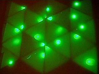
LED SegmentsI've gotten 20 more of these done! That puts me at 152/240, with 2 more needed for this first module. I will probably do them a little tonight and then finish them up Monday or Tuesday. After that, I can stop for a while (thankfully). My fingers are pretty sore and sensitive from the heat and metal.
AssemblyI had to remove one of the pieces of contact paper from one of the pieces of acrylic, because the velcro I had been using just wasn't cutting it (or, more precisely, was burning it from the hot glue). I bought about 30ft of self-adhesive velcro, 3/4" thick, and used a fabric cutting wheel to make nice, straight cuts along it (gotta cut it into thirds!). This works wonderfully, as the adhesive on the velcro is unlike anything I've ever seen. It stick amazingly well to basically everything.
Anyway, I got a new piece of contact paper put on the acrylic and spent a couple hours today putting the velcro on it. The first (bottom) piece of acrylic is now completely done and looks "OK". I say "OK" because there are still air bubbles randomly throughout it and a few minor holes. Not the best job in the world, but I'm now under a small time constraint (read below).
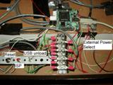
I finally got the processor board mounted to the wall, along with the different switches for reset, ISP, USB unload, and power supply selector. The only switch I have yet to mount is the main on/off switch. The switch I've been using isn't the one that I plan on using, so I haven't made a hole for it yet. Actually, I'm not sure if I will even use a switch right away. It's not entirely needed (the main power switch works fine) and especially not right away.
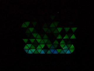
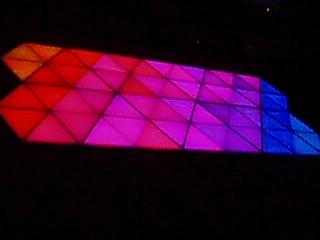
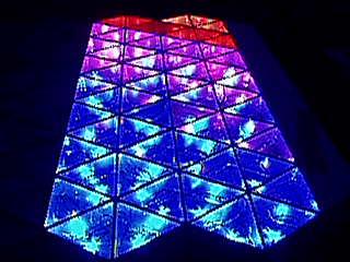
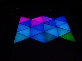
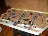
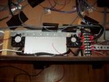
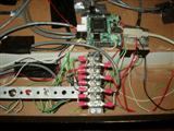
Here're some pictures of the guts behind the pixels (and man is it messy!):
| Internals | Power Supply | Processor Mount | Processor Mount, with labelled switches
|
|---|
| 
|  | 
|
There're still plenty of wires to add, such as power & control cables for the "upper" 3 boards, as well as finalizing the cabling for everything. You can see in the overhead shot that there are orange, purple, and grey clip cables attached to random squiggly wires. These are the reset lines for the boards, and I'm going to be tying them to power directly, but I don't want to route the cables completely yet. Once I get all 6 driver boards working, then I will finish that step.
The processor and switches are mounted on the opposite side as the power supply, with enough room to take up the two remaining compartments (the angled compartment on the end is barely used).
You can also see the two fans (poorly) mounted for cooling. The one on the right blows into the area, whilst the one on the left blows out of it. They probably don't work too well, considering that there are large open areas for the air to simply escape through, instead of cycling the hot air around the power supply. I'm still not entirely sure how much cooling will be needed. I started doing some temperature measurements without the fans running, but the battery for my multimeter died, so I couldn't test any more. After about 3-4 hours of running 1/2 of the pixels in just 1 module at about 20% capacity, it rose from 74F to about 95F. Once I get everything running, I'll try turning all 120 pixels of module 1 on full white and just leave it there for a couple hours. If all goes well, it shouldn't get much above, say, 130F, which is still fine as far as I'm concerned.
I cut a small notch in the internal wall for the power supply source switch, which fit nice and snug in there. It's currently only being held in by duct tape (I don't think "duct tape" is even used by HVAC technicians on ductwork), but that can be "enahanced" with glue later. The other 3 main switches are all mounted on a simple strip of galvanized hanger strap. The large holes worked perfectly for the threading, and it's stable enough for what I need.
The large terminal block looks very similar to the one next to the power supply (which is used for power!), but is for the TWI bus. This seemed like the most effective method of breaking out the bus from the processor to the 6 boards that all require the same signal.
CodingI've begun coding up a few basic tranform functions to apply to the wall. Currently I have:
- Inversion (inverts the colors of all the pixels... red -> cyan, black -> white, yellow -> blue, etc)
- Shift up/down/left/right (shifts all pixels up/down/left/right 1 row)
The inversion can be enhanced to only invert certain channels (e.g. only the red channel)
The shifting functions can either roll over the shifted-out pixels, or just shift in a blank (black) pixel.
If you combine "shift up" with "shift left", for example (or "shift down" with "shift right"), then you get a tranform that shifts all pixels along the upper-left/lower-right axis (there are 3 axes with triangles, not the normal 2 with rectangular ones!). Likewise, combining "shift up" with "shift right" (or "shift down" with "shift left") translates the pixels along the upper-right/lower-left axis.
Simple, but powerful stuff.
Other potential transform functions are
- Average (averages the surrounding 3 or 12 surrounding triangles)
- Rotate (rotates the pixels 60 or 120 degrees about a given pixel)
- Fade (slowly fades the pixel from its current value to black (or white, or any given channel!))
I managed to find, in the documentation, the status bits for controlling the speed of the TWI bus. I think, by default, the transmission speed is set to 62.5 kHz. By setting the speed bits to the fastest setting (266.6 kHz, a 4.3x speed increase), I was able to increase the framerate of the wall by about 50%. This was a very welcome change, indeed.
Hoo-ray!AnnouncementSome of you may have been wondering why there has been a huge bump in the progress in this project over the last 2 months. Indeed, I've put in 27 hours this previous week, and 85 hours since September 1st. Well, there is reason for this, and quite an exciting one (for me, at least).
Now that it's official, and I've committed myself time-wise for it, I feel I can mention that the "technowall" (NOT the official name!) will be part of the upcoming (Artist's reception/opening is on November 17th) video game art show at
Altered Esthetics:
"Level_13: Bonus Round!". Their address at the time of the show is:
Altered Esthetics
1224 Quincy St. NE
Minneapolis, MN 55413
This is just off Broadway and Central; for those that need directions, please consult your
favorite mapping website. If you need more information than this, please contact me.
I will only have the 1st module done, and won't have any computer interface ready, but I will be spending a fair amount of time with coding to get various random (and not-so-random!) patterns working. The pseudorandom seed switch (see the
October 10th post) should keep everything random enough for my needs.
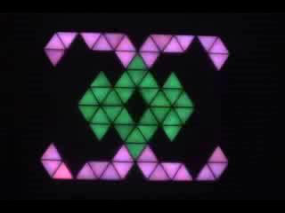
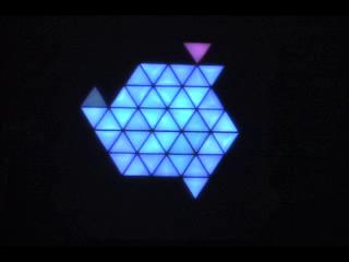
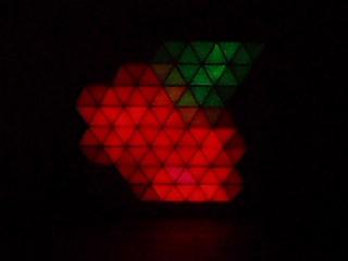
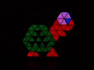
I have already designed several patterns, as well as a few other neat designs, with more to come (hopefully). If anyone wants to try their hand at designing something, here is a PNG template that I've been using:
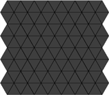
Please email any creations to me! I'd love to see people's creativity with such a small (and oddly-constrained) resolution!
Exciting news!
Labels: Assembly, Coding, Miscellaneous, Soldering
