Jurek and the Amazing Techno, Colored DreamWall

Jurek and the Amazing Techno, Colored DreamWall

The title is mostly a placeholder, as I haven't really figured out a name for it yet. This project is a wall hanging that consists of semi-large triangular pixels using discrete RGB LED's and PWM to control intensity levels of each LED, resulting in a 4096-color display.

Friday, March 31, 2006

LED triplets

11 done! 229 to go!

Labels:

Monday, March 27, 2006

New Website

OK! here we go!

Pictures!
From Tuesday the 21st:
13 wall pieces, assembled as much as they will go:

View showing the slots and joints of the wood pieces:

Head-on view showing the joints and the gaps between the 3 pieces:


More pictures will come now that I've got one whole section completely assembled and glued.

A single LED triplet, 100% done and ready for usage:


Note that there are currently no real markings on the cables to denote red, green, blue, or common power, but the header is marked with an arrow that I used to signify the common power.

Labels:

Construction and LEDs

Construction
I got 1/2 of the inner wall pieces cut (enough to do one of the sections) and glued this weekend, despite having a nasty flu. On Saturday, I glued everything together and let it cure overnight (in my kitchen, even! I had to climb over the top of it just to get to the bathroom).
I have to say that it turned out quite nice. I was slightly worried about the 22" pieces (4 of them) on the edges, as they only had one notch in them and nothing to really "solidify" their orientation. When I had the pieces unglued and just interlocking, they tended to wobble around a bit. I made extra sure of their orientation as I was gluing them and it turned out pretty well. Still no pictures yet (I'm going to have to get some webhosting at some point), so you'll see it when I get to it I guess :D.

I've updated the progress bar to 18.5%, as I still need to attach the first backing piece as well as the exterior walls and the outside floor piece. It might be a little conservative, but oh well. I found some really nice material to use as the pixel floor. It was some 1/8" stuff I initially bought for the exterior walls. It's marker board and has a nice white, shiney surface on it. One that should work excellently as a reflector, rather than the pieces of paper I had envisioned before. I should need 2 pieces for the floor for each section, totalling 5 that I'd need for the whole assembly. (I should only need 1 for both sections for the outer walls). It cuts moderately OK and is decent to clean as well.

LEDs
I got most of the next batch of 14 triplets worked together. I have all of the 4-conductor wire stripped of casing (but not each individual strand). My fingers were hurting too much from stripping, so I ordered up a wire stripper from DigiKey, along with 1250 3/16"x1/2" pieces of heatshrink tubing (about 52 feet) for the LED connections. I figured this would be easier and more cost-economical than buying tons of 1' pieces and cutting them all myself.


The progress bar is updated to 4.5%. After 16 are done, I will be at 6 2/3% done, so this may be slightly conservative as well.

Cheerio!

Labels: ,

Tuesday, March 21, 2006

Update

Construction
I made decent progress over the weekend using the new method. I completely cut up a 2'x4' piece of plywood (1/4", I was able to find some 1/8" stuff so I can go pretty thin), making 13 pieces. 11 are 44" long (the width of the wall) and 2 are 22" long. If you do the math, there's not a whole lot of material left over as waste (48 sq. in. total, out of 576 sq. in., which is 92% utilization).
For the internal walls, I need 54 pieces:
  • 24 @ 44"
  • 6 @ 38.5"
  • 8 @ 33"
  • 8 @ 22"
  • 8 @ 11"
So in overall lengths cut, I am 29% done. In pieces cut percentages, I am 24% done. Again, because of time and noise constraints, I really can't work on it any more until the weekend.
While I was building and testing the strips of wood, I felt nostalgic about the balsa wood dinosaurs that were popular in my youth. I had about a half dozen of them myself and several of my friends had many more than I. Anyone else remember those?

LEDs
I have completely soldered 2 LED triplets (out of the 240 I need), complete with inline resistors, and terminated with a 2x2 header socket. They each took me about 30 minutes to do, but I'm still refining the procedure for doing them, so the time per LED wire will probably drop slightly. Each LED triplet has:
  • 3 LEDs (red, green, & blue)
  • 3 resistors
  • 13 soldering joints
  • 11 pieces of heatshrink tubing
  • 3 twisted pair cables
  • 1 4-conductor cable
  • 4 crimp connectors
  • 1 4-pin socket

Website Updates
I would normally have included pictures with this posting, but the friend that is lending me server space and bandwidth for pictures (evilducks.net) changed hosting companies and hasn't set up an account for me to upload files yet. Pictures will come!

I have added some lame bargraphs on the sidebar to track progress of various aspects of the project. These will be updated whenever I make progress, not only when I make a blog posting. Hopefully, this will help slightly with motivation. We'll see.
I have tried it in Opera, FireFox, and IE. It works properly in Opera and FireFox, but the bars don't show up in IE. Stupid IE. I'm not a web expert, so I don't know how to fix it so it does. If anyone knows CSS well enough to take a look at the code, let me know and I can send you the template to look at. (Or if you can discern it just by looking at the HTML, then by all means go ahead and try and let me know!)

Labels: , ,

Friday, March 17, 2006

Changes, Progress Reversal, and Updates

Changes & Progress Reversal
OK, so I think I've completely decided on switching over to the new construction method. It will afford me many more benefits than my current construction. I will only be losing about 20 hours or so of work and about $100 worth in lumber that can't be used any more.

The new method is similar to what other people have been doing, and I don't know why I never thought of it before. The only major difference is that I need to intersect 3 pieces of wood, instead of their two (triangles, instead of squares).
For reference, see this post and this image:


The big split between halves half-way down will still be there, but everything else will be changing. My plan is to have the pixel walls be about 2" tall (I could maybe go smaller too) and be about 1/2" thick plywood. I would use 1/4" plywood, but I need to have the outer walls be 1/2 the thickness of the inner walls. This way, I can abut any two wall sections seamlessly.
Every 5.5" (the pixel length), there will be one or two slits, depending on which axis the wood piece is, that extend a full 2/3 of the height of the wood, leaving only 1/3 (~0.66") of the wood remaining for structural integrity. The three axes of wood lengths will then be slotted and glued together (I shouldn't need anything more than glue for them; they're strong even without glue). This will give me a pseudo-honeycomb (except triangles instead of hexagons).
Then I can just affix a piece of plywood to the bottom (the thinner, the better) and I basically have the entire enclosure (minus the acrylic top, of course). On the outer walls, I was planning on using 1/4"-thick plywood, like I said, but it would be 3" tall, instead of 2". This would give me a subfloor with which I can mount the electronics and run the wiring. Since I won't be having any border around the wall, I need everything completely self-contained.

Well, almost completely. There's still the issue of the power supply. It's a full 2"x3.75"x5.8". Which means that I could mount it in an enclosure that hangs down an extra ~4" on the bottom of the bottom wall "module".

I should be able to have all of the connectors between the bottom and top modules (USB, power, SPI, and switches), as well as connectors for modules to the left and right of each of them, flush with the edge of the wall. The 1" margin on the bottom will be enough for this.


Updates
I spent a whopping $18 on 70 feet of heat shrink tubing and 100' of 2-conductor 26ga. wire at Ax-Man today. I figured I should spend as little as possible for just testing. I got maily 1/8" tubing, with some 3/16" as well. The 1/8" is a little too big for what I need and it was as small as they had, so if I were to get more, I would get 1/16" or 3/32", depending on what suppliers had available. The wire worked decently and I finally figured out a way to solder the wires to the resistors and LEDs. The only problem is that it took a moderate amount of time, so I have a long way to go. I now have one LED triplet done (yay 0.4% completed!) and I've verified that it works. It's just over 19" long, so it should be long enough to go from the board to the furthest-away pixel. That's one nice thing about having separate driver boards; I can have the boards centered around the pixels they're powering and not have to deal with LED wiring that're several feet long.

Tomorrow, I must go buy lots of wood and start cutting. I will have to come up with a way to make 4'-long cuts in plywood with a jigsaw go fast and straight. I have 54 2"-tall pieces to cut and 36 3"-tall pieces to cut. Fun, fun!

Labels: ,

Wednesday, March 15, 2006

Potential changes

I was thinking about the construction as I laid in bed last night. I may end up ditching all the construction work I've done so far. I can't really do any testing until the weekend, but I'll keep you posted.

Also, I'm in a sort of quandry about the computer side of the coding. I have no idea where to start to be able to communicate with the microcontrollers, outside of using the programming software (not really an option). If anyone has any ideas about how to go about using USB interface libraries (in C, C++, C#, Java, Python, whatever...), please let me know.

Labels: ,

Construction Progress

Construction
I've made pretty decent progress over the last week with construction of the wall. I am now up to 7 pieces attached: 3 outer walls, 2 inner floors, and 2 inner walls. Things are starting to finally come together. I've got a decent system for attaching the pieces together, even though right now it seems sorta flimsy. I think that once I start attaching the outer wall pieces (the smallish zig-zag pieces that are 5.5" long), the inner floor and walls will stiffen up.

Just in case it doesn't start firming up, I came up with a way to hopefully stabilize everything.
In these pictures:


You can see that the inner walls are attached to the inner floor pieces using angle brackets. The amount of wood sticking out on the bottom of the inner walls is such that I can only use one of the holes of the brackets, leaving another one just sitting there. I've been lining up these brackets for the last 4 mounted (as you can see in the top picture). What I have planned is using a 3' threaded rod through each set of brackets (4 threaded rods per wall section, 2 wall sections total) and then using screws on either side of the bracket pairs to adjust their positions if needed.

More pictures!
Top-down view of the top side:


Side views:


I had been playing around with different ideas for attaching the aluminum flashing to the wall. What I had initially decided on was to cut one large piece that zig-zagged all the way across a given pixel row (essentially being 4.4"x14, which is 61.6" long) and then attach it using carpet tacks. I was very leary about the first and eventually abandoned the idea yesterday in favor of doing single 4.4" long pieces (14 of them of course). I still had an uneasy feeling about using the carpet tacks to attach them to the wood. I initially tried using wood glue, but that failed miserably.
I was getting ready to go about using the carpet tacks, even taping down the pieces with duct tape when it dawned on me. I had this fear of using duct tape in the final version of it, for absolutely no reason. The pixels were going to be filled with aluminum foil anyway, so what would a little duct tape hurt? It turned out pretty well, as you can see from the pictures below, and was a helluva lot easier, less error-prone, and more error-recoverable (if I screwed up with the carpet tacks, then I end up with a bunch of small holes in the plywood) than using the carpet tacks.

Close-up of the pixels with aluminum flashing for pixel dividers, affixed with duct tape (The pencil marks are how the actual pixel divisions end up):


Distance sensor:


I decided to pull out the distance sensor just to see how it fit with the inner walls. My idea is to cut out a recess in the inner walls for the sensors, so that they end up flush with the top of the wall, like everything else. The connector will stick into a pixel a little bit, but I don't think it'll be anything major.

Labels:

Friday, March 10, 2006

Construction and Testing

Construction
I now have 3 pieces of wood attached to each other. These are the real-deal pieces and I've taken great care in aligning them and making sure that all the nail holes are correct before doing it. I used wood glue along the floor plywood and outer wall joint as nails really aren't enough. On the inner wall connection, I've only used 4 L-brackets without any glue, as I need these sections to be able to be disassembled (for now). At this point, I just need to start cutting more floor plywood pieces so I can continue.

Testing
I've done a bit more testing on my soldered uC board tonight. I soldered on the reset switch, ISP switch, and USB unload switch and verified that Windows can recognize it when I perform the correct switch incantation ritual. The uC programming software correctly connects to it and I've successfully programmed code to the device. Whee, yet another hurdle checked off.

I also extended the LED blinking program (BLINKY) to send signals to all 32 I/O ports available (the P4.1 & P4.2 are used solely for the TWI) and verified with LEDs that they all work. So far, so good.

The only major things I haven't tested yet are the ADCs. I have a bunch more to do, like get the TWI working with the driver boards, so I have a bit of testing yet to do before I get to that stage. As a simple test of the ADCs, what I've envisioned is just hooking up LEDs to each I/O port and then have it be a 32-position bar chart, displaying the values returned by the ADC. I can then test this on each of the channels of both chips (there are 8 channels per chip).

Progress marches on!

Labels: ,

Monday, March 06, 2006

The Good, the Bad, & the Better

Wow... what a week.

The Bad
On Sunday (the day after my previous post), I decided to pull out the microcontroller board and test out the processor. I also had plans on trying out the processors I bought for this purpose, so I didn't have to use the one that came with the starter kit as well as plans to test my newly-finished uC board.

I pull out the board, dust it off, put the processor in, and hook it up. Nothin'. Windows says it doesn't know what the hardware is and that I should unplug it and plug it back in. !*@* I play around with things for a while: I try reinstalling the software; I try a different uC; I try using a different computer. Still nothing. Ugh...

I check DigiKey to order another one. They have 1 (!!!!!) in stock, and it's for $82 instead of their normal $132. At least something's looking up. I also need to order a bunch of resistors, as I finally found a good match for mixing. 280 Ohms for red, and 69.8 Ohms for both green and blue. These values are driving red at 10mA and both green and blue at 20mA. Go figure, the red at the same mcd power is twice as powerful as green or blue. Oh well...
So I add 500 69.8 Ohm resistors and 250 280 Ohm resistors to my shopping cart (240 pixels) and I add in a few random switches to test out for the reset button, voltage source, USB unload switch, and ISP switch and off my order goes... ZOOM!!! I love 2-day ground shipping for $5.

The Good
So then Tuesday rolls around and I get my uC starter kit board #2, 750 resistors, and switches. I didn't have any time to play around with them at all Tuesday or Wednesday, so they sat awaiting my involvement until Thursday. Thursday rolls around and I pull the new starter kit out and hook it up. Wonderfully (and expectedly), it works on the first try.

OK... now what?

I take the new processor out of the new starter kit and stick it in the old starter kit. It works perfectly...
I take the old processor and put it in the new starter kit. It works perfectly...
I take the old processor and put it in the old starter kit. IT works perfectly...

AUGH!!!!!!!!!!

So my stupid self actually had the processor in wrong. I had it rotated 90 degrees and had just assumed that the package of the processor or the socket wouldn't allow me to do that. Oh well... not all is lost.
What this allows me to do now is to use the SPI (Serial Peripheral Interface) (or even the TWI for that matter) to do inter-uC communication testing. Whee, what fun! I played around a little bit and (thought I) managed to get the two processors to communicate properly. Oh what joy abounds!... almost. It turns out that that wasn't the case at all.

I had also ordered through Techni-Tool a bunch of different supplies, including a new circuitboard vise, solder reel, tip tinner, and (most-importantly) a smoke absorber. They are scheduled to arrive on Tuesday, so I can continue my soldering fun then!

The Better
OK, so Saturday, I dive back into the board and try to do more with the inter-uC communication. I turned the slave board on and noticed that the light patterns were exactly the same as I was seeing before, except this time it wasn't hooked up to the master board.
After some debugging, I found out that there is a pin on the SPI wire set (there are 6 on the starter board) that is called SS. This stands for Slave Select and is only supposed to be asserted if it is supposed to be the slave that is being communicated to. I had these hooked up to each other, so I'm sure they were just freaking out about who was the slave. Anyway, Atmel had some sample code that didn't use the SS line, so I just used that instead.

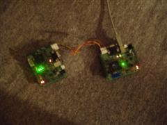
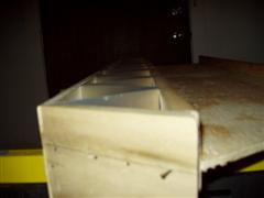
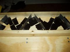
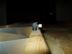
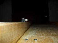
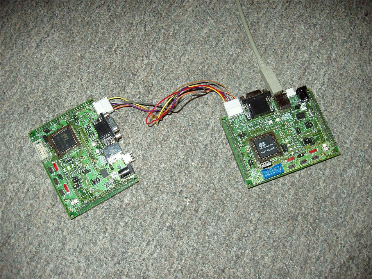
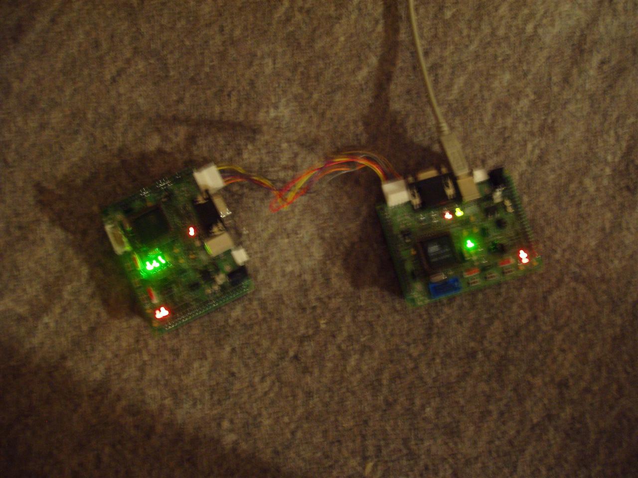
Two starter kit boards, hooked together via SPI. Note that the slave board isn't being connected via USB to anything; it's getting its power from the SPI bus.


Lit version:


Quicktime Movie (2.33MB):


I got a pretty non-random pattern to successfully be transferred from the master to the slave uC and it appears to work properly this time.


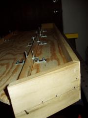
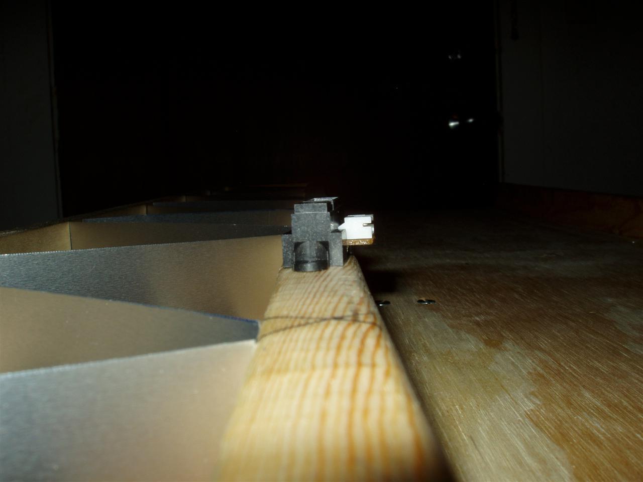
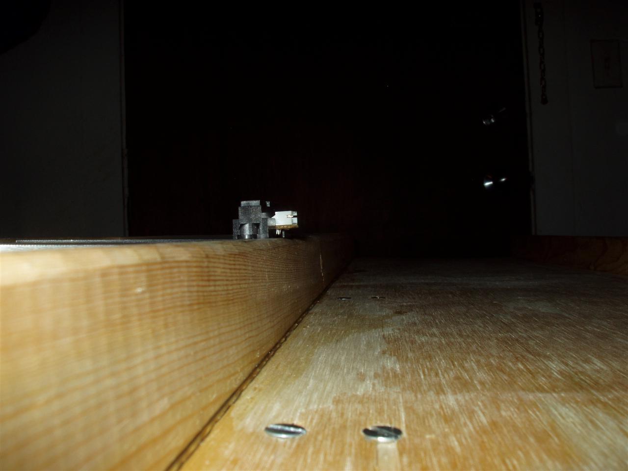
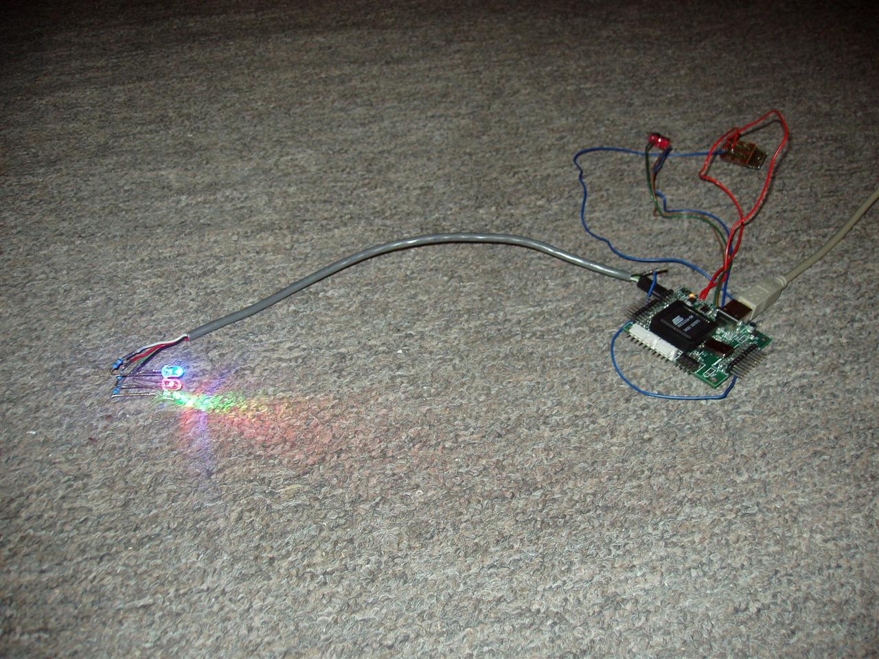
I also got a wild idea to test my as-of-yet untested uC board that I finished soldering a couple weeks ago. I reprogrammed the uC to just randomly blink the LEDs on the test board (which use Port 3 of the uC) and then dropped the uC into the test board. What followed made me very joyous and I breathed a very big sigh of relief. What this amounts to is that the board had been started 7 months ago, involved many different steps and revisions, caused me many headaches, and kept me up at night wondering if the core component would actually work. Huzzah! (No one says "Huzzah!"... sheesh...)

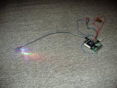
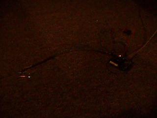
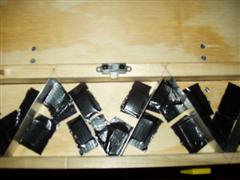
Picture of the setup:


Quicktime movie of the lights a-blinkin' (1.05MB):


The Caveats (special feature!):
  • For some reason, the voltage regulator is outputting at 4V instead of 3.3V, but the chips I use support up to 5.5V, so that's no biggie.
  • I haven't tested either of the ADCs on the board
  • I also haven't tested the USB data port (the computer never recognized the device when I plugged it in, so I'm sorta suspect about that)
  • Nor have I done an exhaustive test on the ports (only a few pins of Port 3)
  • I also haven't tested the current limiter on the USB port, so that may or may not work either. It wouldn't be the end of the world if that didn't work, however.
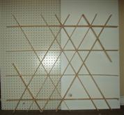
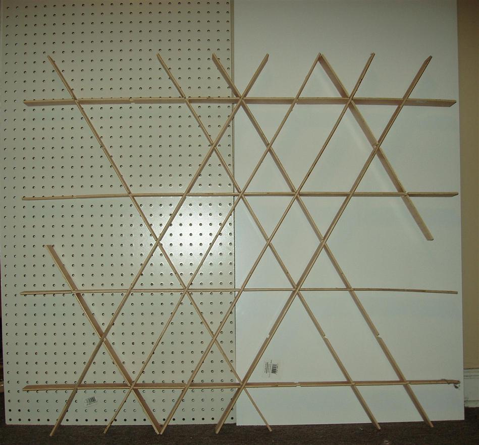
  • I still have to figure out how to solder the LEDs together on a piece of wire. The one piece I soldered together looks like crap and won't work at all. Plus, I have to do 240 of them. Fun, fun!

Labels: ,